
Temperature protection device

Active Publication Date: 2013-06-13
NISSAN MOTOR CO LTD
View PDF4 Cites 34 Cited by
  • Summary
  • Abstract
  • Description
  • Claims
  • Application Information

AI Technical Summary

Benefits of technology

The present invention is about a device that prevents semiconductor elements from getting too hot and improves the accuracy of detecting when they are.

Problems solved by technology

Thus, noise is added to the detection signal, which decreases the temperature detection precision of the switching element.
As a result, there is the potential for erroneous operations to occur in order to attempt protect the switching element from overheating, when in actuality no overheating is occurring.

Method used


Image

  • Temperature protection device
  • Temperature protection device
  • Temperature protection device

Examples


Embodiment Construction

[0015]Selected embodiments will now be explained with reference to the drawings. It will be apparent to those skilled in the art from this disclosure that the following descriptions of the embodiments are provided for illustration only and not for the purpose of limiting the invention as defined by the appended claims and their equivalents.

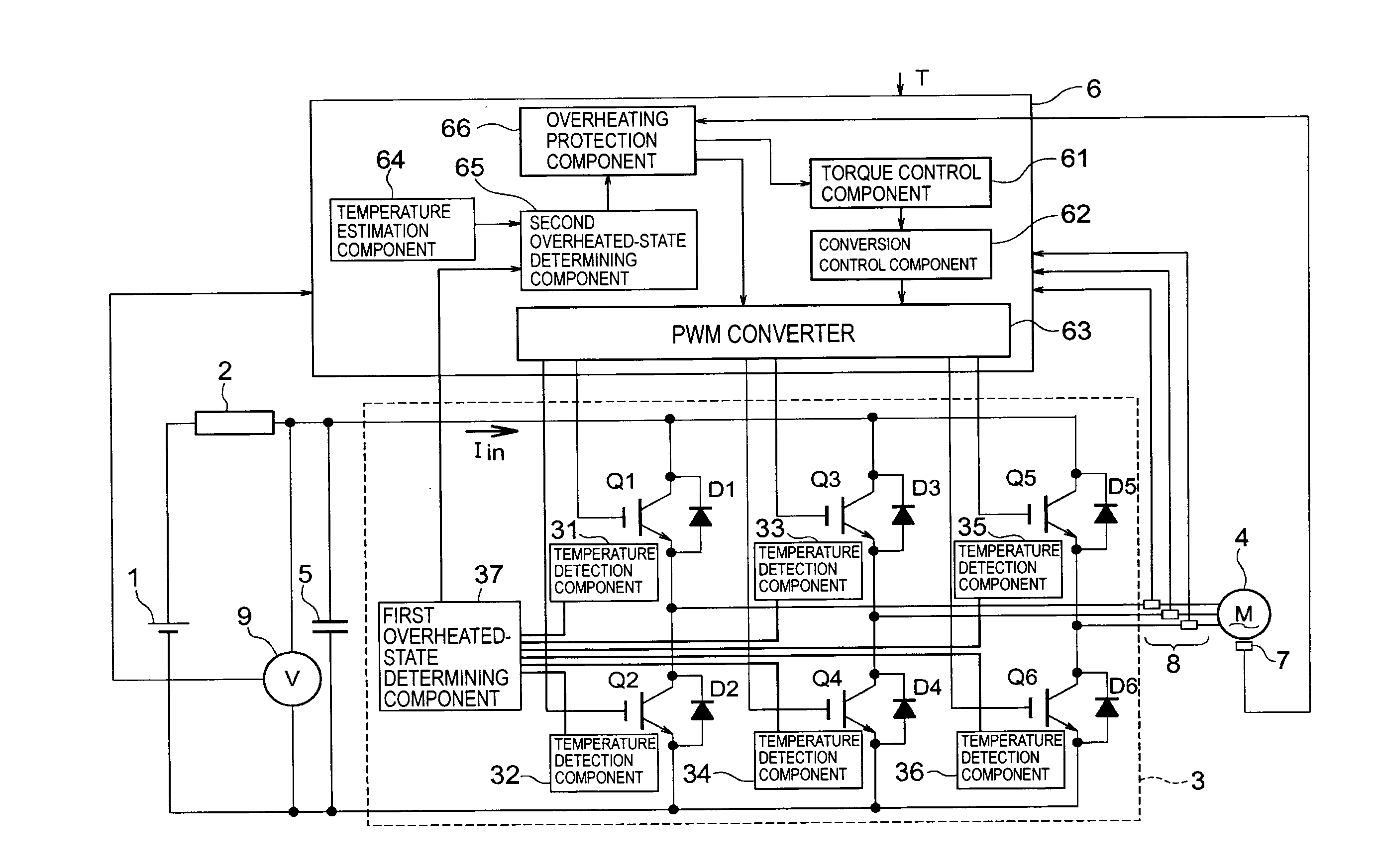
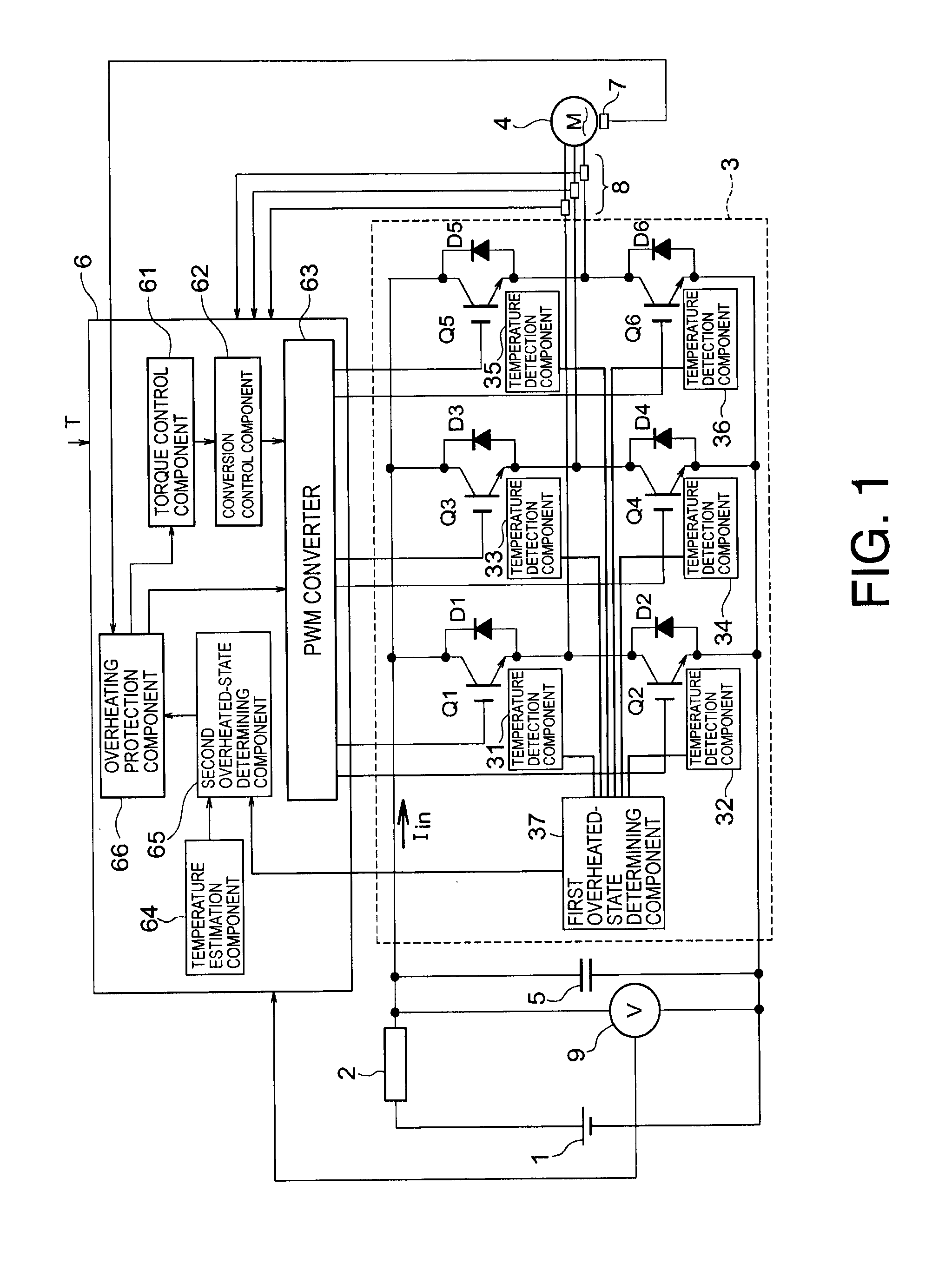
[0016]Referring initially to FIG. 1, a motor control device for an electric vehicle is illustrated in accordance with a first embodiment. FIG. 1 is a block diagram showing the motor control device that includes a temperature protection device of a first embodiment. The motor control device includes a battery 1 that is electrically connected to the semiconductor module 3. The battery 1 serves as a power source for a permanent magnet motor 4 having a three-phase current output as the travel drive source. The semiconductor module 3 converts the DC power from the battery 1 to AC power. A secondary cell (not shown), such as a lithium ion cell, can be m...


PUM


Abstract

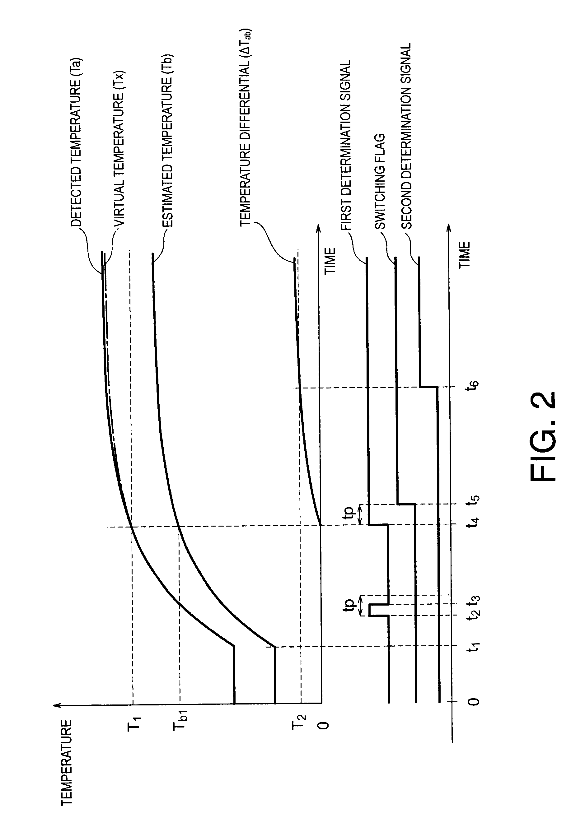
A temperature protection device basically includes a temperature detector, a temperature estimator, an overheated determining component and an overheating protection component. The temperature detector detects a temperature of a semiconductor component. The temperature estimator estimates an estimated temperature of the semiconductor component. The overheated determining component determines whether the semiconductor component is in an overheated state based on the detected temperature and the estimated temperature by using a first estimated temperature as the estimated temperature at a time point when the detected temperature has reached a first threshold temperature and a second estimated temperature that is estimated subsequent to the time point as the estimated temperature when the detected temperature has reached the first threshold temperature. The overheating protection component protects the semiconductor component from the overheating based on a determination made by the overheated determining component.

Description

CROSS-REFERENCE TO RELATED APPLICATIONS[0001]This application claims priority to Japanese Patent Application No. 2010-217307, filed on Sep. 28, 2010. The entire disclosure of Japanese Patent Application No. 2010-217307 is hereby incorporated herein by reference.BACKGROUND[0002]1. Field of the Invention[0003]The present invention generally relates to a temperature protection device. More particularly, the present invention relates to a temperature protection device that is able to more precisely determine an overheated state of a semiconductor device of, for example, a motor control device, to more reliably protect the semiconductor device from overheating.[0004]2. Background Information[0005]Typically, a power-converter temperature protection device can be provided on the cooling fan for the main circuitry of an inverter. For example, as described in Japanese Unexamined Patent Application No. H-121595, a power-converter temperature protection device can include a temperature sensor ...

Claims


Application Information

Patent Timeline
IPC IPC(8): G01K3/04H02P29/00H02H7/12H02P27/06
CPCH03K2017/0806H03K17/0828H02P29/0088G01K3/04H02P29/68
Inventor KAWAMURA, HIROMICHI
Owner NISSAN MOTOR CO LTD
Learn More