Auto-zero amplifier and feedback amplifier circuit using the auto-zero amplifier

a feedback amplifier and amplifier technology, applied in differential amplifiers, amplifiers with semiconductor devices/discharge tubes, amplifier details, etc., can solve the problems of increasing the circuit scale, unable to compensate the offset voltage due to a temperature drift,

Active Publication Date: 2013-06-13
FUJI ELECTRIC CO LTD
View PDF4 Cites 77 Cited by
  • Summary
  • Abstract
  • Description
  • Claims
  • Application Information

AI Technical Summary

Problems solved by technology

This, however, has a problem in that the compensation of the offset voltage due to a temperature drift becomes impossible.
This, however, has a problem in that two auto-zero amplifiers are required to result in an increase in the scale of the circuit.

Method used


Image

  • Auto-zero amplifier and feedback amplifier circuit using the auto-zero amplifier
  • Auto-zero amplifier and feedback amplifier circuit using the auto-zero amplifier
  • Auto-zero amplifier and feedback amplifier circuit using the auto-zero amplifier

Examples


Embodiment Construction

[0022]In the following, explanations will be made in detail with respect to certain embodiments of the invention.

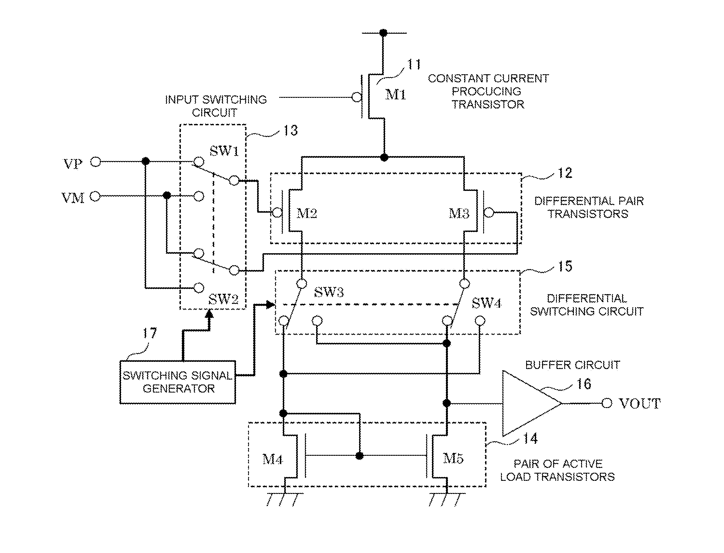
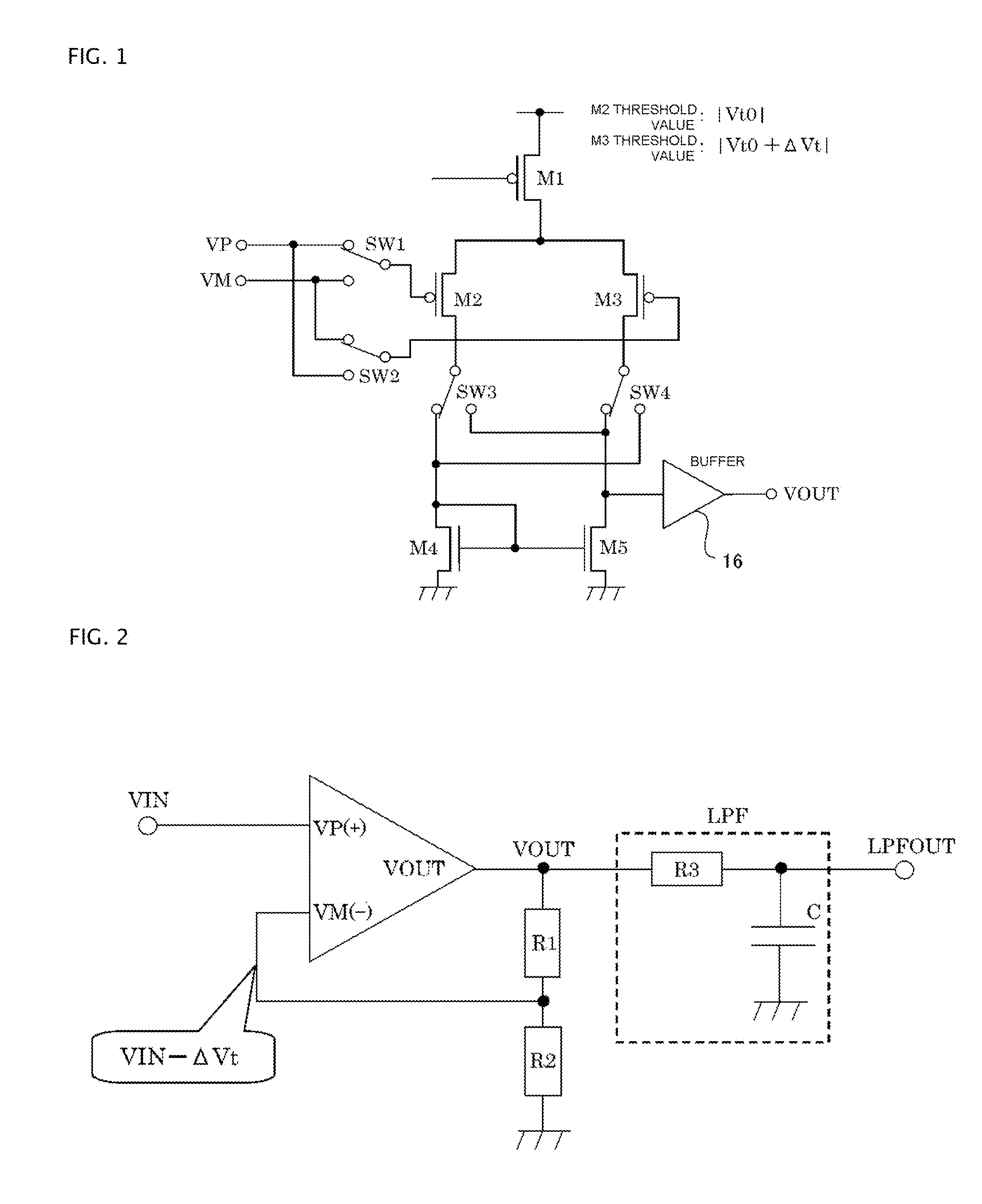
[0023]FIG. 1 is a circuit diagram (part 1) showing a circuit configuration of an auto-zero amplifier according to embodiments of the invention. Here, the circuit of the auto-zero amplifier shown in FIG. 1 is applicable to any feedback amplifier circuit using an OP amplifier circuit. Explanations will be made, however, with respect to an example of a positive phase amplifier circuit. Moreover, FIG. 2 is a circuit diagram (part 1) showing the whole circuit configuration of a feedback amplifier circuit using the circuit of the auto-zero amplifier shown in FIG. 1.

[0024]In FIG. 1 and FIG. 2, input terminals of the circuit of the auto-zero amplifier are designated as VP (non-inverting (+) input terminal) and VM (inverting (−) input terminal) and an output terminal of the circuit is designated as VOUT. In FIG. 1, reference sign M1 designates a constant current producing transist...


PUM


Abstract

In aspects of the invention, at normal operation, an operational amplifier circuit has feedback applied from the output thereof to the input thereof so that currents equal to each other flow in differential pair transistors, respectively. While, in order that currents equal to each other may flow in the differential pair transistors, respectively, for compensating the difference in threshold voltages in the differential pair transistors, a voltage lower by a certain voltage difference than the voltage applied to the gate terminal of the transistor must be applied to the gate terminal of the transistor. From this, the switching of switches, when a virtual short circuit occurs, can make the output voltage of the operational amplifier circuit become a signal in which positive and negative rectangular ripples, with the values thereof being proportional to the value of the certain voltage difference, are superimposed on a true value.

Description

BACKGROUND OF THE INVENTION[0001]1. Field of the Invention[0002]Embodiments of the invention relate to auto-zero amplifiers and a feedback amplifier circuits using auto-zero amplifiers.[0003]2. Related Art[0004]FIGS. 8A-8C illustrate circuit diagrams showing a circuit configuration and operations of the circuit of an auto-zero amplifier as an OP (operational) amplifier circuit according to the related art.[0005]The operations of the circuit of the auto-zero amplifier according to related art shown in FIG. 8(A) may be classified into two phases, one of which is a compensation phase as shown in FIG. 8(B) and the other one of which is an operation (actual use) phase as shown in FIG. 8(C).[0006]First, the operation in the compensation phase shown in FIG. 8(B) will be explained. In the compensation phase shown in FIG. 8(B), with switches SW_A shown in FIG. 8(A) being closed, switches SW_B shown in FIG. 8(A) are opened. At this time, the circuit shown in FIG. 8(A) comes to form a voltage ...

Claims


Application Information

Patent Timeline
Patent Type & Authority Applications(United States)
IPC IPC(8): H03F3/45H03F1/34
CPCH03F2203/45618H03F3/45179H03F2203/45588H03F3/45475H03F1/342H03F3/45986H03F2203/45544H03F2203/45614H03F2203/45674H03F3/45968H03F2203/45562H03F2203/45684H03F2203/45724H03F2203/45681H03F2203/45536H03F2203/45644H03F2203/45616H03F3/45183
Inventor IWAMOTO, MOTOMITSU
Owner FUJI ELECTRIC CO LTD
Why Eureka
Try Eureka