Clip terminal for fixing case and shield apparatus using the same

a technology for shield devices and terminals, which is applied in the direction of printed circuit components, electrical apparatus casings/cabinets/drawers, support structure mounting, etc., can solve the problems of reducing the mounting area of shield devices, affecting the mounting effect of shield devices, and reducing the mounting area of devices. , to achieve the effect of minimizing the mounting area and easy fitting

Active Publication Date: 2013-06-13
KIM SUN KI +1
View PDF6 Cites 23 Cited by
  • Summary
  • Abstract
  • Description
  • Claims
  • Application Information

AI Technical Summary

Benefits of technology

[0010]An object of the present invention is to provide a clip terminal which allows a case to be easily fitted and minimizes a mounting area on a circuit board.

Problems solved by technology

Thus, it may be difficult to fit the lower end of the sidewall of the shield case into the metal clip due to a small alignment margin of the metal clip.
Also, when the shield case is manufactured through a press process including cutting and bending, a gap may occur in a corner of the shield case with the corner cut.
Thus, when the shield case is repeatedly mounted or separated, the gap may be more widened to reduce EMI shielding efficiency.
However, since the clip terminal should have the L-shaped bent part, the process of manufacturing the clip terminal may be complicated.
Thus, when a reflow soldering process is performed and the clip terminal is picked up, it may be difficult to mount the clip terminal at a desired position on fused solder cream having low viscosity due to large shake of the clip terminal.
Thus, the clip terminal may be incongruous with existing electronic equipments in which a high-density mounting technology is required.
These problems are not limited merely to the clip terminal for fixing the EMI shield case, but may also occur in a clip terminal for fixing a case which protects internal electronic components against external impacts.

Method used


Image

  • Clip terminal for fixing case and shield apparatus  using the same
  • Clip terminal for fixing case and shield apparatus  using the same
  • Clip terminal for fixing case and shield apparatus  using the same

Examples


Embodiment Construction

[0043]Now, preferred embodiments of the present invention will be described in detail with reference to the accompanying drawings.

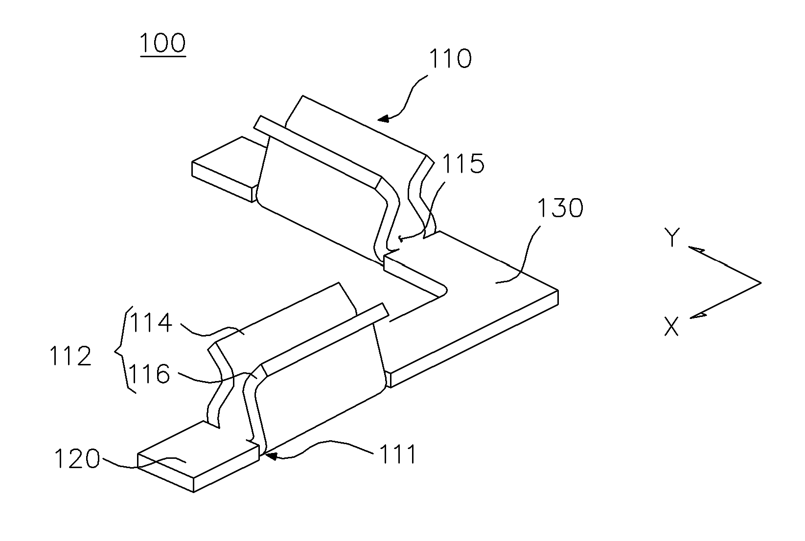
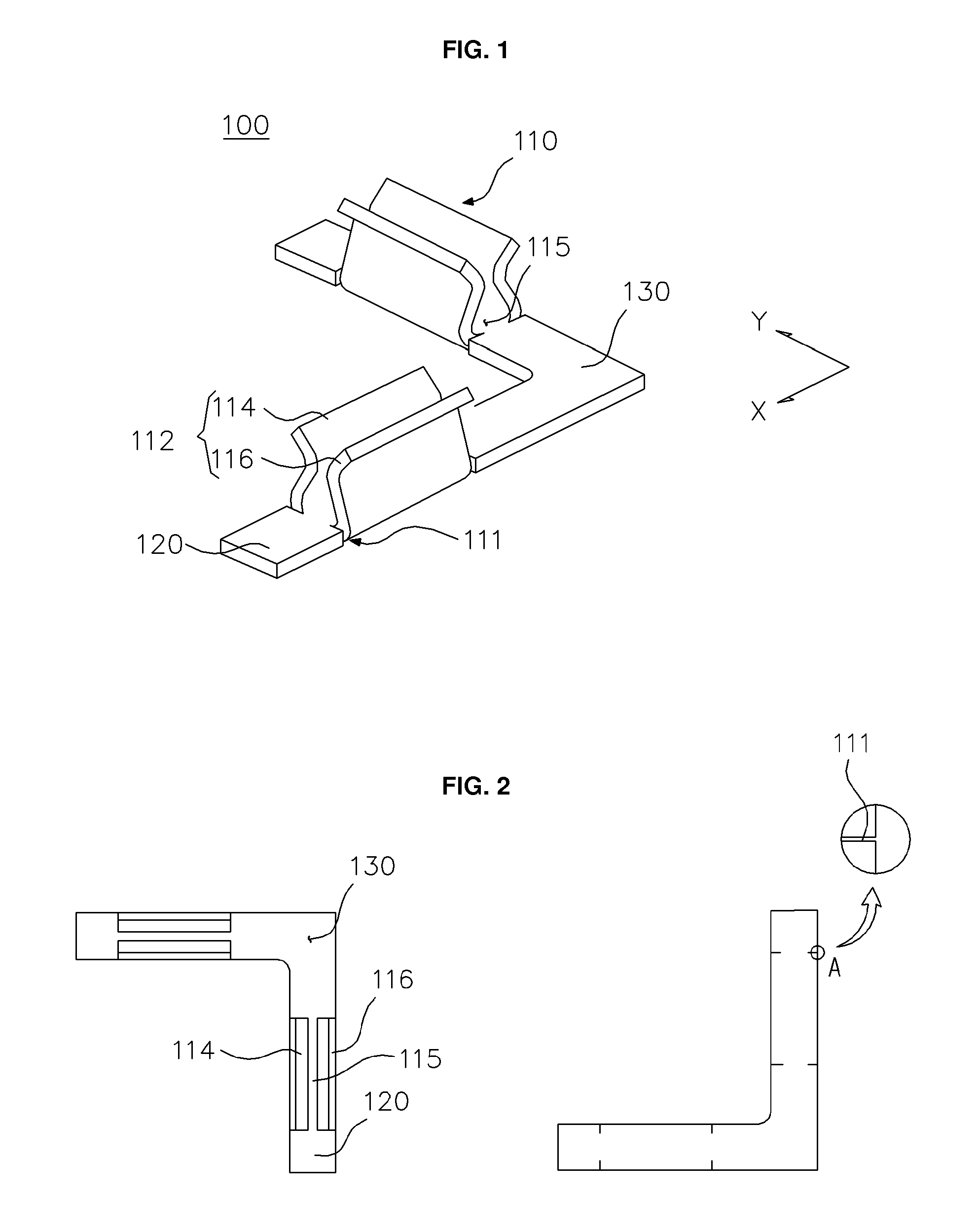
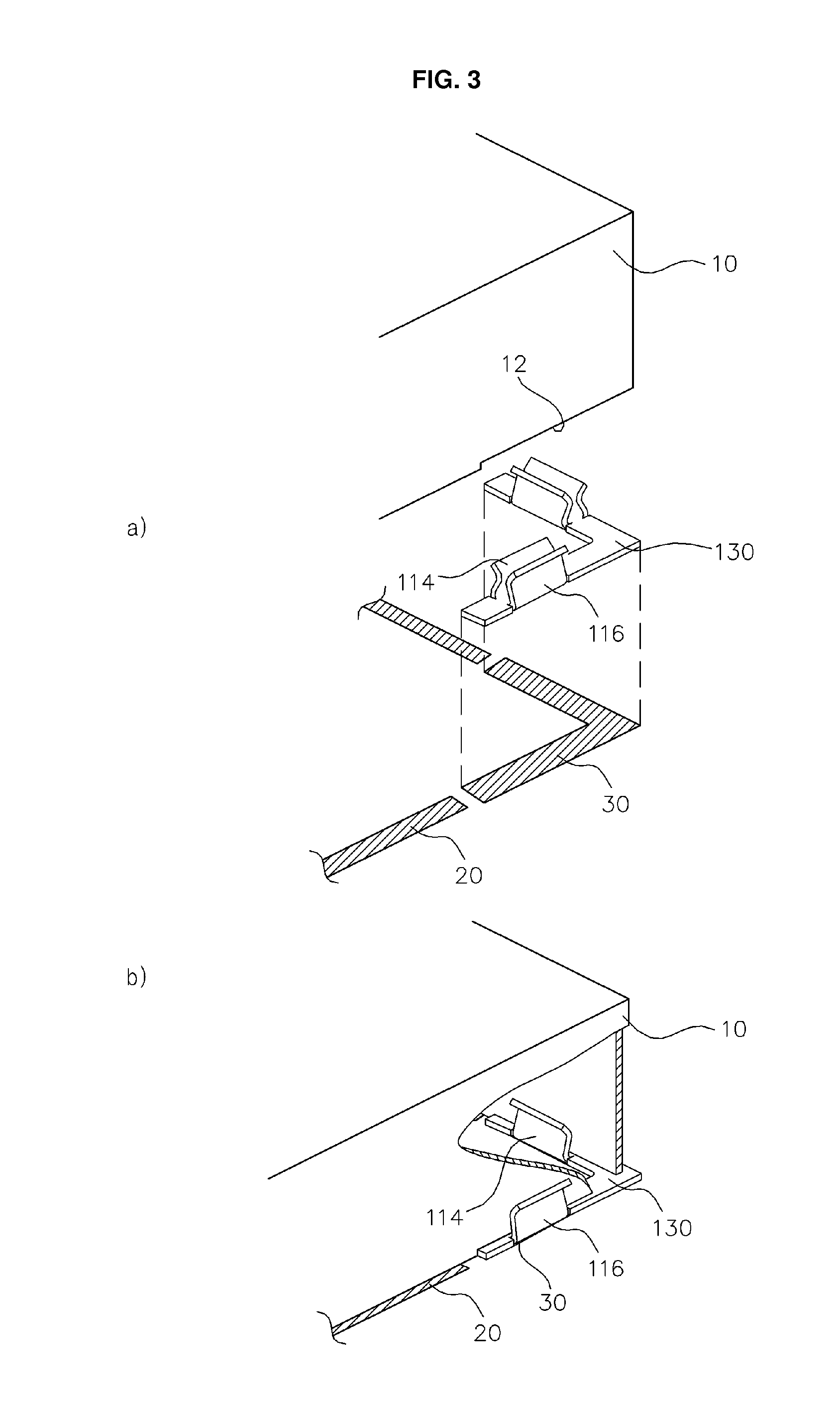
[0044]FIG. 1 is a perspective view of a clip terminal according to an embodiment of the present invention. FIG. 2 is plan and bottom views of the clip terminal. FIGS. 3(a) and 3(b) illustrating a state in which the clip terminal of FIG. 1 is soldered using solder cream disposed on a solder pattern to fix a case.

[0045]A clip terminal 100 according to an embodiment of the present invention includes a connection part 130 bent at an angle corresponding to that of a corner of a case 10, e.g., an angle of about 90° and a pair of clips 110 integrally disposed on both ends of the connection part 130. Selectively, auxiliary fixing parts 120 may extends outward from ends of the clips 110, respectively.

[0046]Referring to FIG. 3, the connection part 130 has a width equal to or less than that of a solder pattern 30. Also, each of the auxiliary fixing parts 120 and the...


PUM


Abstract

A clip terminal soldered to and mounted on a circuit board, includes a connection part bent at an angle corresponding to that of a corner of a case and at least a pair of clips connected to each other by the connection part. The connection part and the clips are integrated with each other. The connection part has a width less than or equal to that of a solder pattern of the circuit board on which the clip terminal is soldered. A lower end of the corner of a sidewall of the case is fitted into the clips.

Description

REFERENCE TO RELATED APPLICATIONS[0001]This application claims the priority benefit of Korean Patent Application No. 10-2011-0131822 filed on Dec. 9, 2011, and Korean Patent Application No. 10-2012-0038438 filed on Apr. 13, 2012, the entire contents of which are incorporated herein by reference.FIELD OF THE INVENTION[0002]The present invention relates to a clip terminal for fixing a case, and more particularly, to a clip terminal which is used for fixing a case to a solder pattern of a circuit board. Furthermore, the present invention relates to an electromagnetic interference (EMI) shield apparatus in which a clip terminal is fitted into a corner of an EMI shield case and integrated therewith.BACKGROUND OF THE INVENTION[0003]EMI shield cases are used to prevent electromagnetic waves generated in high frequency electronic components or modules, which are used for electronic equipments and information communication equipments, from leaking to the outside or protect the high frequency...

Claims


Application Information

Patent Timeline
Patent Type & Authority Applications(United States)
IPC IPC(8): H05K7/14
CPCH05K9/0035H05K9/00H05K3/341H05K2201/10371H05K2201/10962H05K7/1417H05K9/0009H05K9/0024H05K7/12H05K9/0032H05K7/14H05K7/1405
Inventor KIM, SUN-KI
Owner KIM SUN KI
Why Eureka
Try Eureka