Low bay lighting apparatus

a lighting apparatus and low-bay technology, applied in lighting and heating equipment, fixed installations, lighting support devices, etc., can solve the problems of metal halide lamps that require extremely high pressure to operate, generate high temperatures during operation, and substantial injury in the workplace or during maintenan

Active Publication Date: 2013-06-13
MCGEHEE MICHAEL EUGENE +1
View PDF6 Cites 13 Cited by
  • Summary
  • Abstract
  • Description
  • Claims
  • Application Information

AI Technical Summary

Benefits of technology

[0015]The general aspect of the apparatus may further provide a plurality of mating locking clips configured to prevent the plurality of spring clips from being operated to release the modular light source from the light fixture when the mating locking clips are inserted into the spring clips.
[0018]The general aspect of the apparatus may further provide that the light fixture and the mounting bracket further include one or more locking fastener receivers configured to accept a fastener to prevent the plurality of posts from sliding in the plurality of slots, the locking fastener receivers of the light fixture having a location that corresponds with a location of the locking fastener receivers of the mounting bracket.
[0025]The general aspect of the apparatus may further provide a modular power supply configured to supply power to the plurality of modular LED boards, the modular power supply and the plurality of modular LED boards being sealed and watertight, a watertight hand-operated power cord configured to connect the modular power supply to a source of electricity, and a plurality of watertight hand-operated connector cords configured to supply the plurality of modular LED boards with power from the modular power supply. The watertight power cord and the plurality of watertight connector cords are further configured to prevent water damage to the plurality of modular LED boards and the modular power supply, and allow connection to and disconnection from the modular power supply and the plurality of modular LED boards without using tools or termination of the source of electricity.

Problems solved by technology

However, metal halide lamps require extremely high pressures to operate, and generate high temperatures during operation.
Even so, due to the high stress of operation, metal halide lamps are often subject to explosions and, thus, have the potential to cause substantial injury in the workplace or during maintenance.
Further, low bay lighting applications that implement LEDs consume much less power than a typical metal halide lamp.
However, low bay lighting applications implementing LEDs still suffer from many drawbacks.
For example, related low bay lighting applications that implement LED technology do not take into account heat buildups caused by boundary conditions created within the lamp that creating high thermal resistances.
These one-piece sealed units make component or LED replacement extremely difficult without compromising seals and ratings.
Compromise of those seals and ratings often serve to invalidate the warranty of the fixture.
In addition, conventional low bay fixtures implementing LEDs are generally unable to be maintained in the field and must be removed to be serviced.
Moreover, the subsequent removal of the conventional low bay fixtures implementing LEDs requires an electrical supply to be disconnected or shut down.

Method used


Image

  • Low bay lighting apparatus
  • Low bay lighting apparatus
  • Low bay lighting apparatus

Examples


Embodiment Construction

[0045]The following description is provided to assist the reader in gaining a comprehensive understanding of the methods, apparatuses, and / or systems described herein. Accordingly, various changes, modifications, and equivalents of the methods, apparatuses, and / or systems described herein will be suggested to those of ordinary skill in the art. The progression of processing steps and / or operations described is an example; however, the sequence of steps and / or operations is not limited to that set forth herein and may be changed as is known in the art, with the exception of steps and / or operations necessarily occurring in a certain order. Also, descriptions of well-known functions and constructions may be omitted for increased clarity and conciseness.

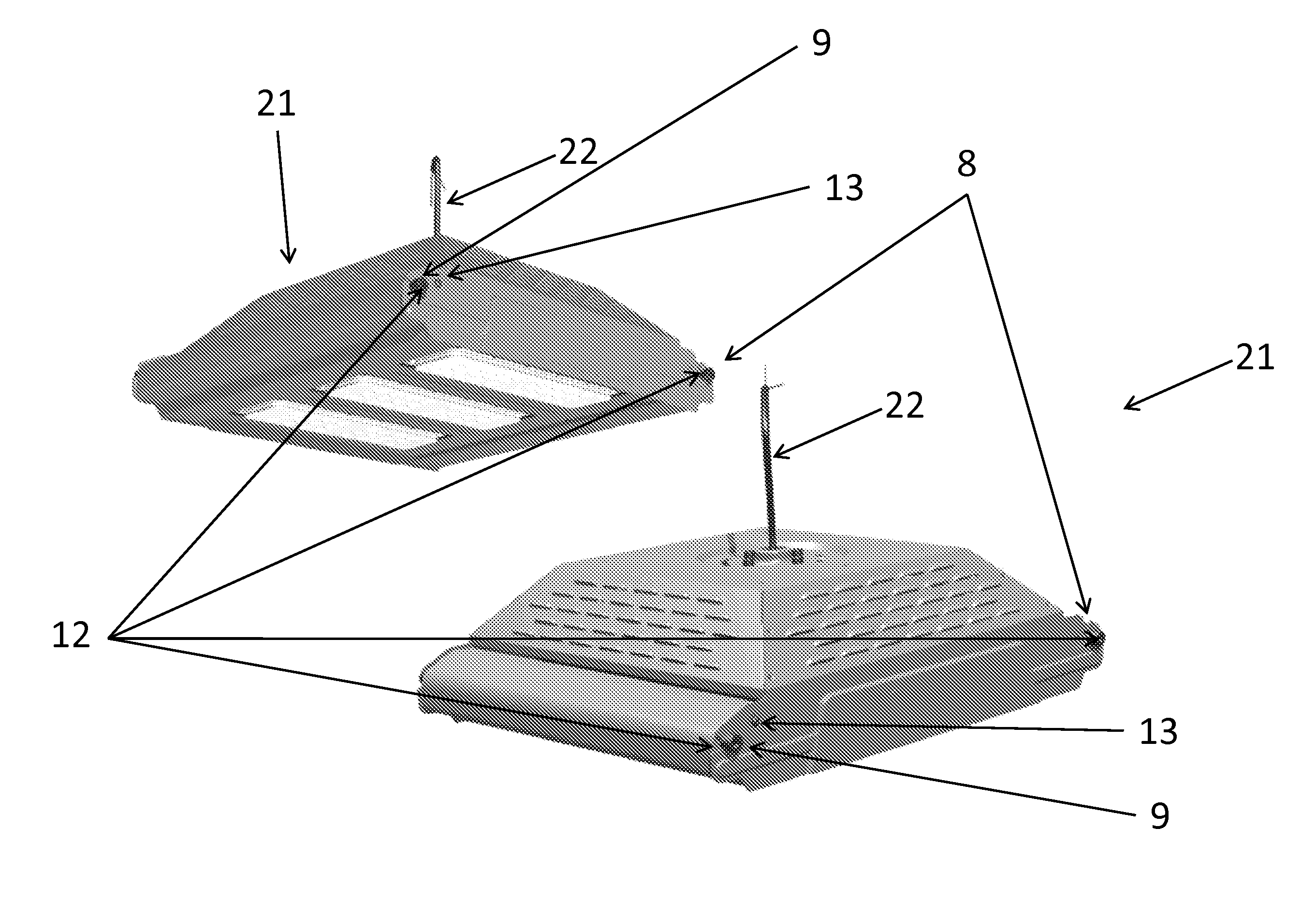
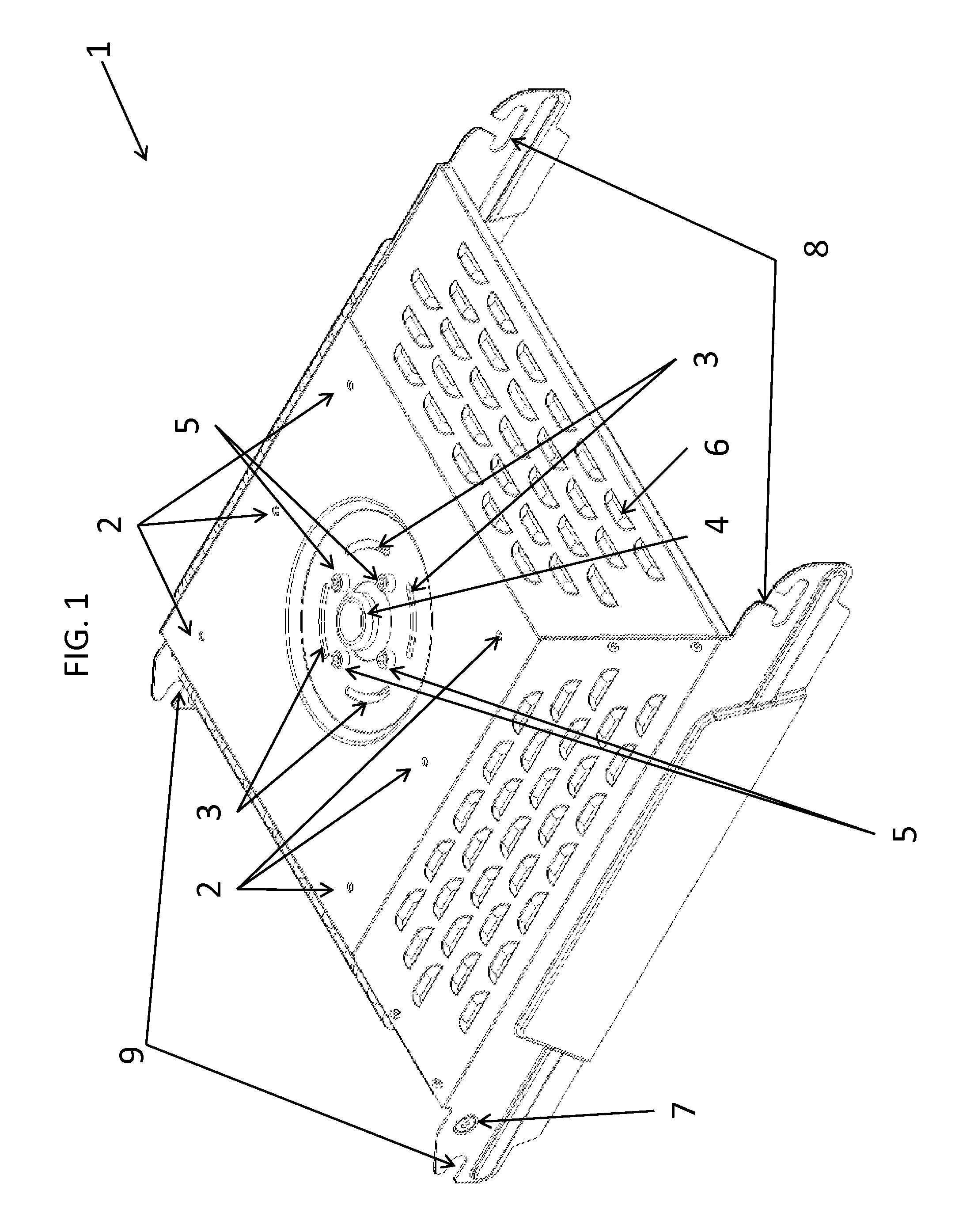
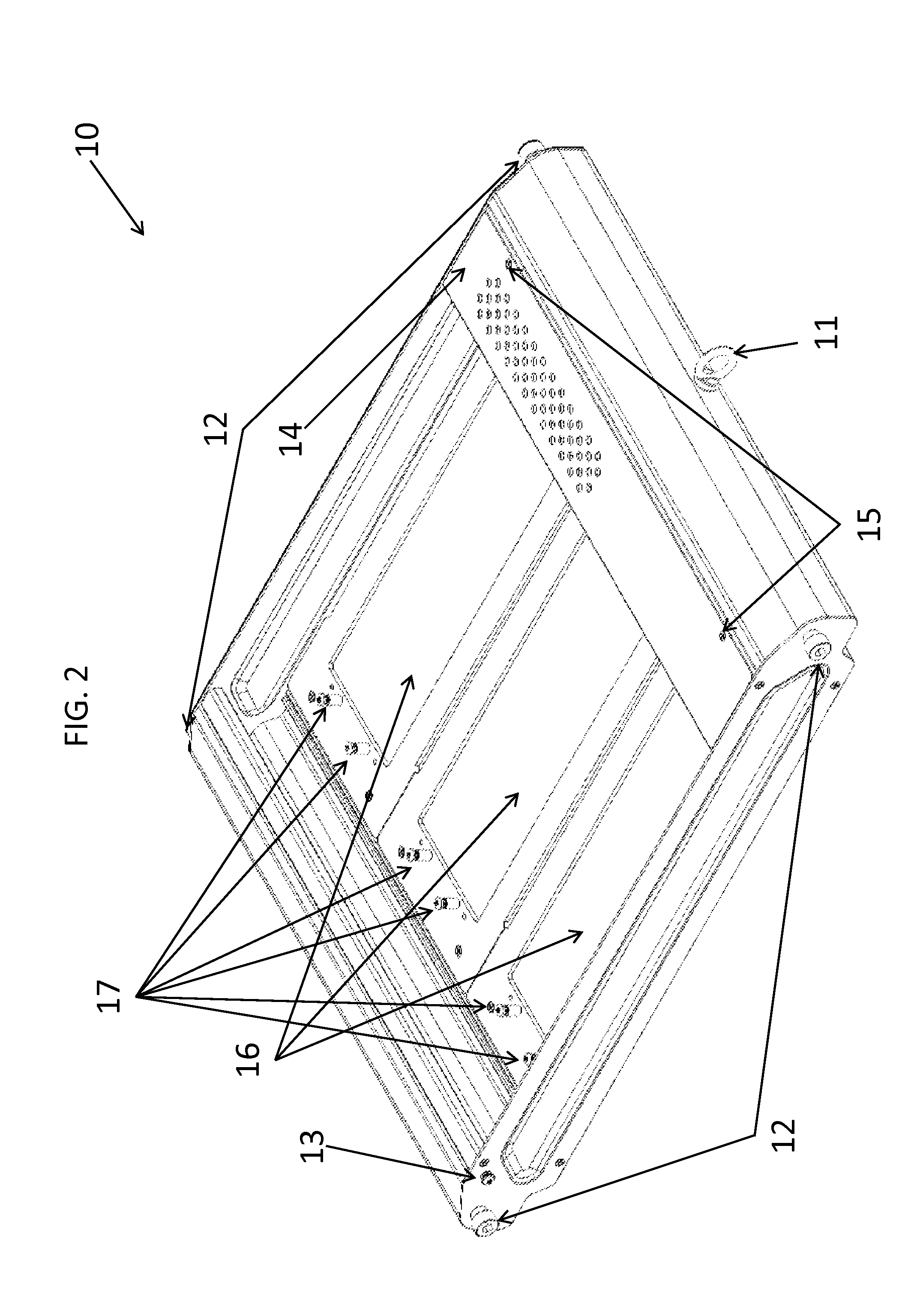
[0046]A low bay lighting apparatus 21 includes a mounting bracket 1 and a light fixture 10. The mounting bracket 1 and the light fixture 10 may be fabricated from any one of a number of different powder-coated metals. FIG. 1 illustrates ...


PUM


Abstract

There is provided a low bay lighting apparatus secured to an elevated horizontal surface, the low bay lighting apparatus including a light fixture, including a modular light source configured to illuminate areas disposed beneath the light fixture, a modular power supply configured to provide power to the modular light source, and a plurality of posts disposed on planes that are perpendicular to a long side of the modular light source and on opposite ends of opposing outer side surfaces of the light fixture, and a mounting bracket secured to the elevated horizontal surface, the mounting bracket including a plurality of slots configured to mate respectively with the plurality of posts to removably secure the light fixture to the mounting bracket.

Description

CROSS-REFERENCE TO RELATED APPLICATION[0001]This application claims the benefit under 35 U.S.C. §119(e) of U.S. Provisional Application No. 61 / 072,073, filed on Dec. 8, 2010, in the United States Patent and Trademark Office, the entire disclosure of which is incorporated herein by reference for all purposes.BACKGROUND[0002]1. Field[0003]The following description relates to general, commercial, and industrial illumination, and, more particularly, to a low bay lighting apparatus configured to illuminate general, commercial, and industrial environments while being serviceable on site without disconnection of electricity or removal of the low bay lighting apparatus from its affixed location.[0004]2. Description of the Related Art[0005]Low bay lighting solutions are implemented in a variety of general purpose, industrial, and commercial illumination environments, such as the illumination of parking structures, transportation garages, warehouses, assembly areas, gyms, hangars, retail spac...

Claims


Application Information

Patent Timeline
Patent Type & Authority Applications(United States)
IPC IPC(8): F21V21/08F21V21/088
CPCF21S8/026F21V19/001F21V29/83F21Y2101/02F21V29/76F21V19/045F21V19/04F21K9/20F21Y2115/10
Inventor MCGEHEE, MICHAEL EUGENEADINOLFI, JOHN THOMAS
Owner MCGEHEE MICHAEL EUGENE
Why Eureka
Try Eureka