

Power Conversion Device
a technology of power conversion device and switching element, which is applied in the direction of power conversion system, ac-dc conversion without reversal, electrical apparatus, etc., can solve the problems of substantially double the amount of loss and substantially double the number of switching elements, and achieve the effect of reducing costs and losses
- Summary
- Abstract
- Description
- Claims
- Application Information
AI Technical Summary
Benefits of technology
Problems solved by technology
Method used
Image

Examples
first embodiment
[0030]The first embodiment of the present invention will be described.
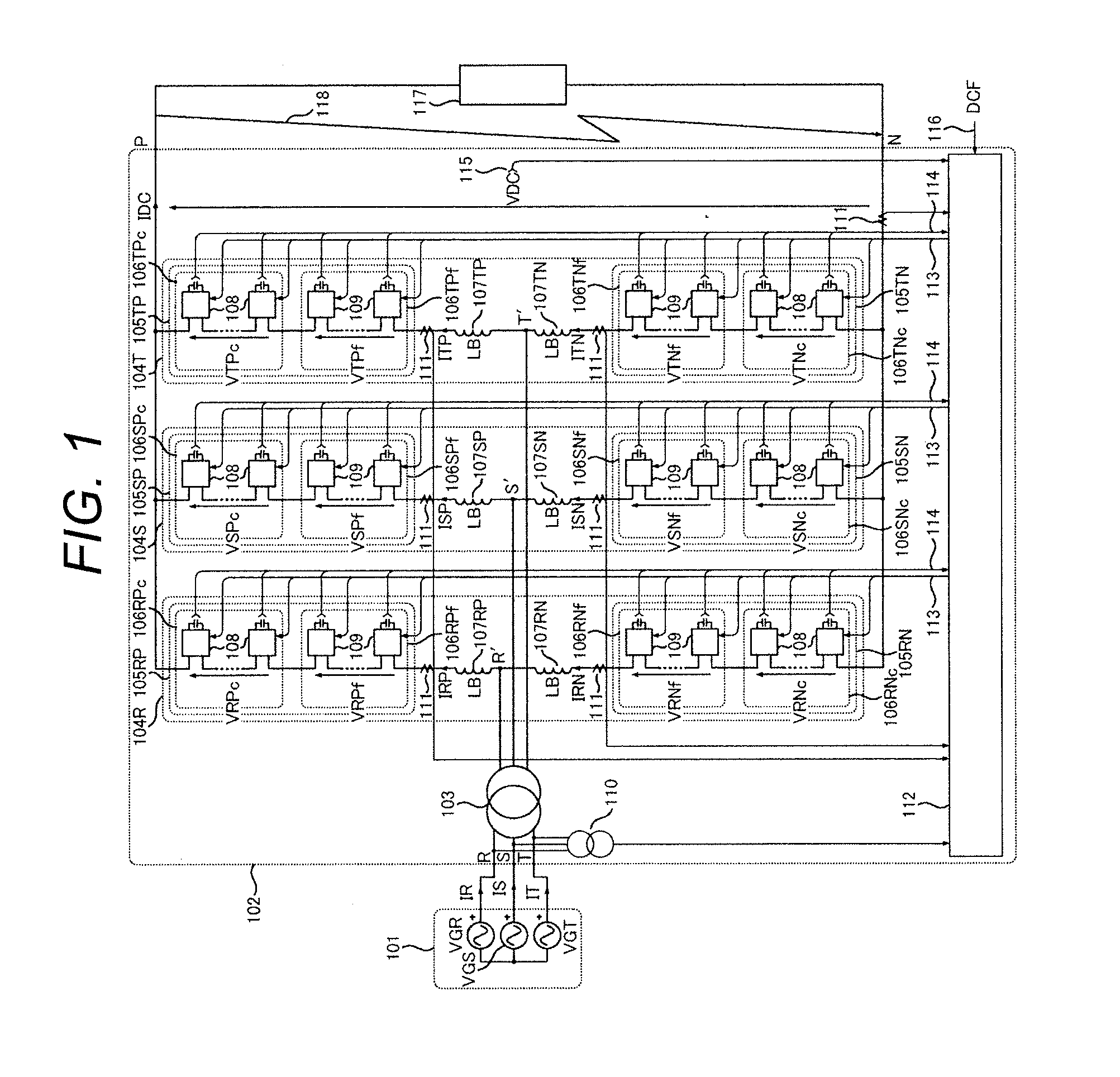
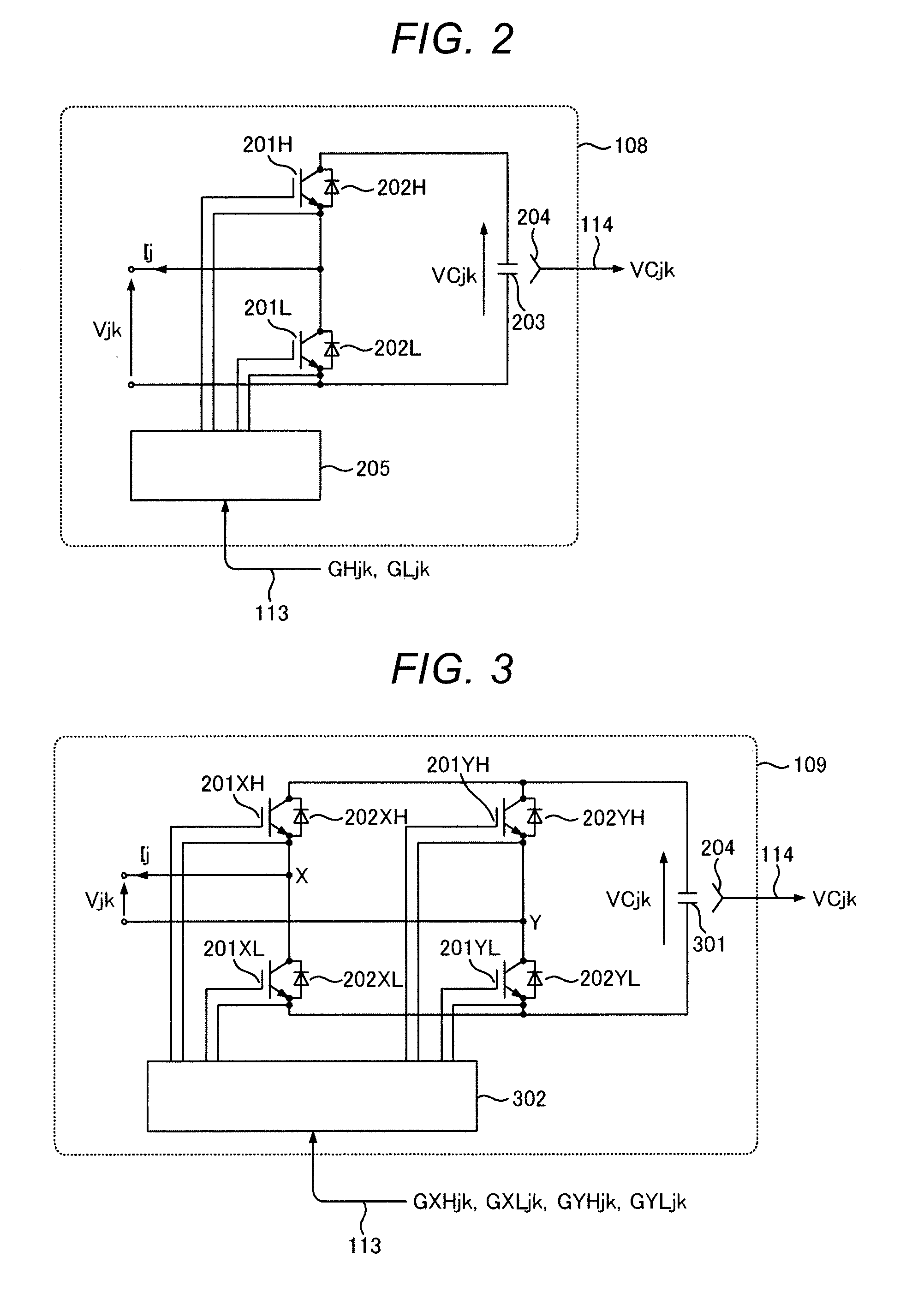
[0031]In the first embodiment, each arm is constituted by two kinds of unit converters including a full bridge type unit converter and a bidirectional chopper type unit converter.
[0032]In a case of using a switching element with the same rating as that of the MMCC-DSBC in the related art, it is possible to achieve an effect of reducing the number of switching elements to about ¾ in the first embodiment.
[0033]Hereinafter, a configuration according to the first embodiment will be described with reference to FIG. 1. After the configuration is described, an operation principle according to the present embodiment and schematic operation waveforms will be described.
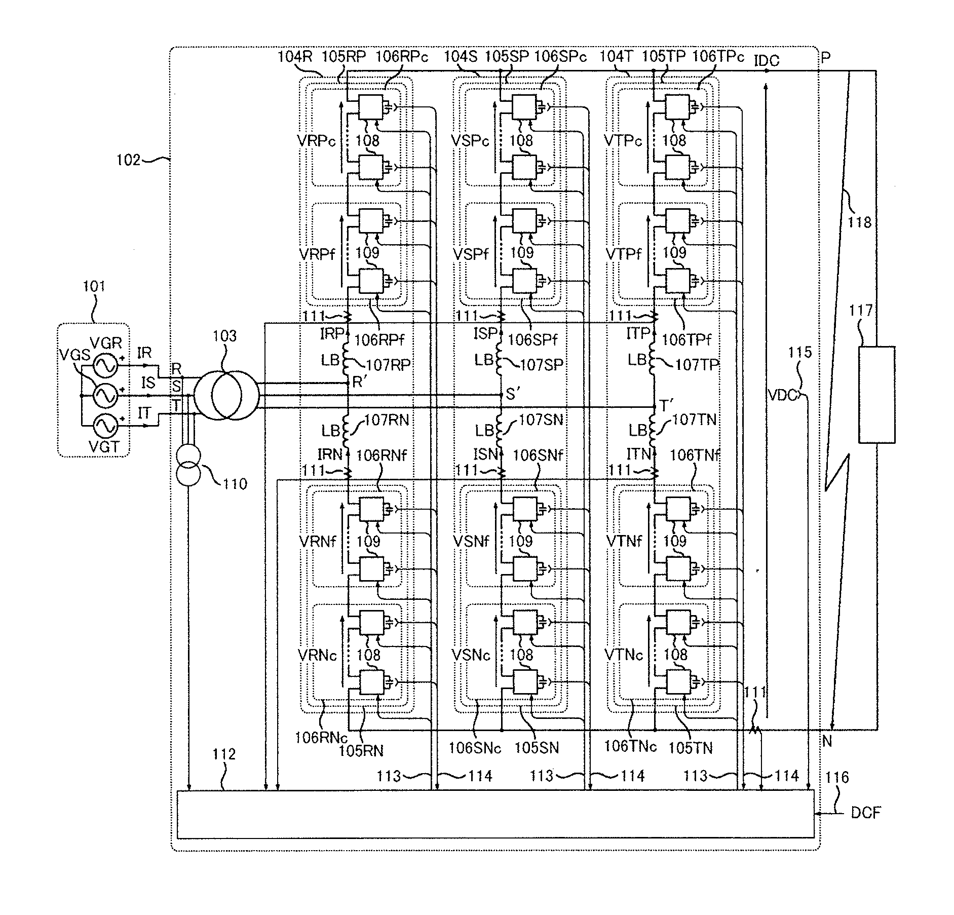
[0034]First, a description will be made of a connection state between a power conversion device 102 and external circuits.
[0035]The power conversion device 102 is connected to an AC system 101 via a transformer 103. In the present embodiment, the AC system 10...
second embodiment
[0164]The second embodiment of the present invention will be described.
[0165]The second embodiment is characterized in that the command value distribution unit 701 shown in FIG. 7 is employed instead of the command value distribution unit 504 according to the first embodiment.
[0166]In the same manner as the first embodiment, in a case of using switching elements with the same rating as that of the MMCC-DSBC, it is possible to achieve an effect that the number of switching elements can be reduced to about ¾.
[0167]Hereinafter, description regarding FIGS. 1 to 4 showing the common configuration to the first embodiment will be omitted, and an operation of the command value distribution unit 701 shown in FIG. 7 used instead of FIG. 5 will be described.
[0168]As shown in Expressions (21) to (24), the R phase AC voltage command value VR* and the DC voltage command value VDC* are distributed to an output voltage command value VRPc* of the bidirectional chopper group 106RPc, an output voltage...
third embodiment
[0199]The third embodiment of the present embodiment will be described.
[0200]As compared with the power conversion device 102 shown in FIG. 1 according to the first and second embodiments, a power conversion device 1101 of FIG. 11 described in the present invention is characterized in that a double Y-connection transformer 1102 is used instead of the transformer 103 and the reactors 107RP, 107SP, 107TP, 107RN, 107SN and 107TN.
[0201]In the present embodiment, it is possible to achieve an effect of the reactors 107 can be omitted in addition to the effects achieved by the first and second embodiments.
[0202]Hereinafter, a configuration according to the third embodiment will be described with reference to FIGS. 11 and 12, and the description is restricted to differences from the first and second embodiments.
[0203]The double Y-connection transformer 1102 has a P side secondary winding 1203P and an N side secondary winding 1203N described later. In addition, FIG. 12 shows a winding struct...
PUM
 Abstract
Description
Claims
Application Information