
USB charging module

a charging module and usb technology, applied in the direction of batteries, data exchange chargers, instruments, etc., can solve the problems of inability to charge the day usb hub is incapable of charging a downstream usb device, and the most usb devices cannot be charged in an optimal manner, so as to achieve the effect of superior technique for optimal charging of usb devices

Active Publication Date: 2013-06-13
VIA TECH INC
View PDF7 Cites 27 Cited by
  • Summary
  • Abstract
  • Description
  • Claims
  • Application Information

AI Technical Summary

Benefits of technology

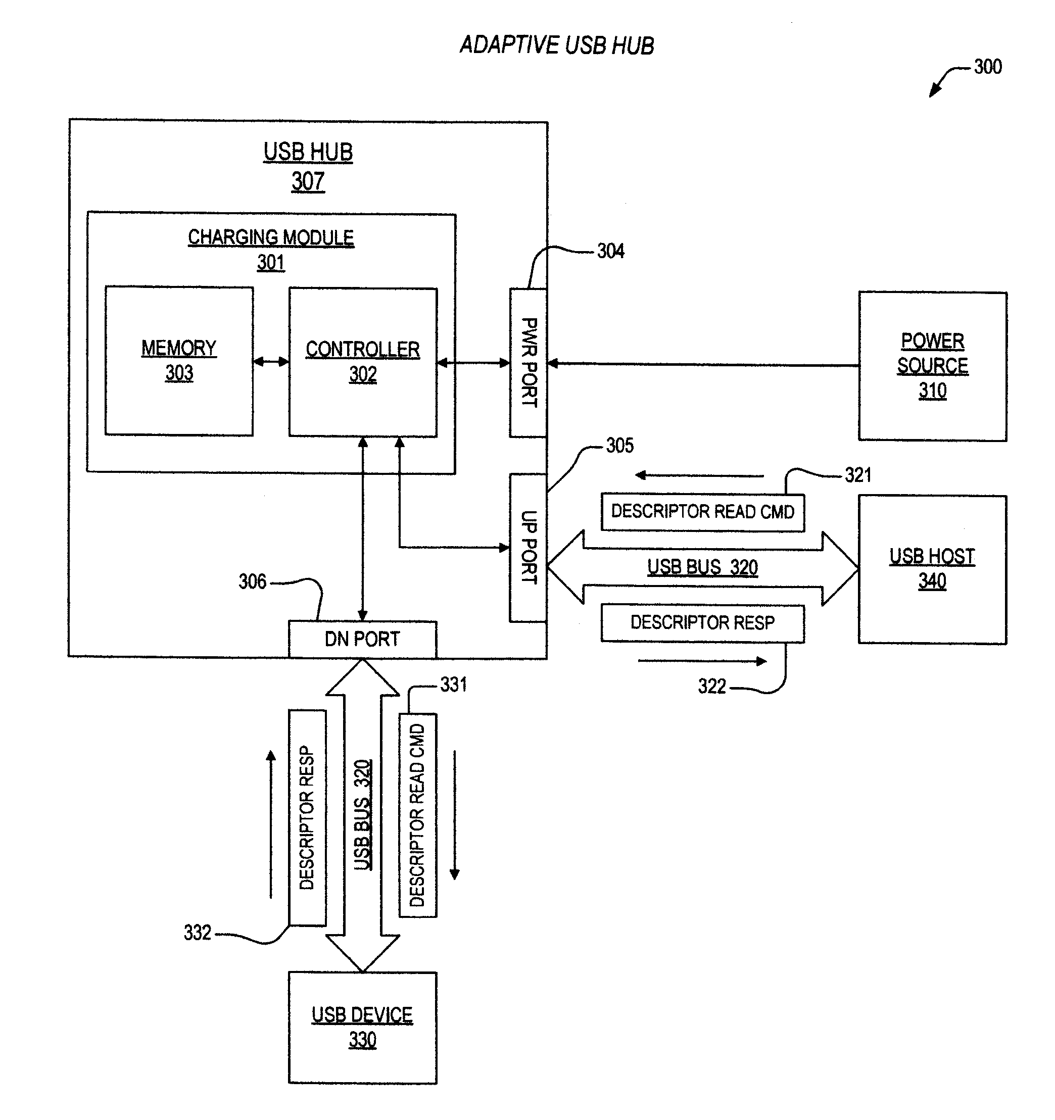
The present invention provides a better way to charge USB devices. An apparatus is provided that uses an optimal charging mode based on a descriptor obtained from the USB device. The apparatus includes a charging module with a memory and a controller that matches the descriptor to a specific entry in the memory and initiates the optimal charging mode based on the charging data. This allows for faster and more efficient charging of USB devices.

Problems solved by technology

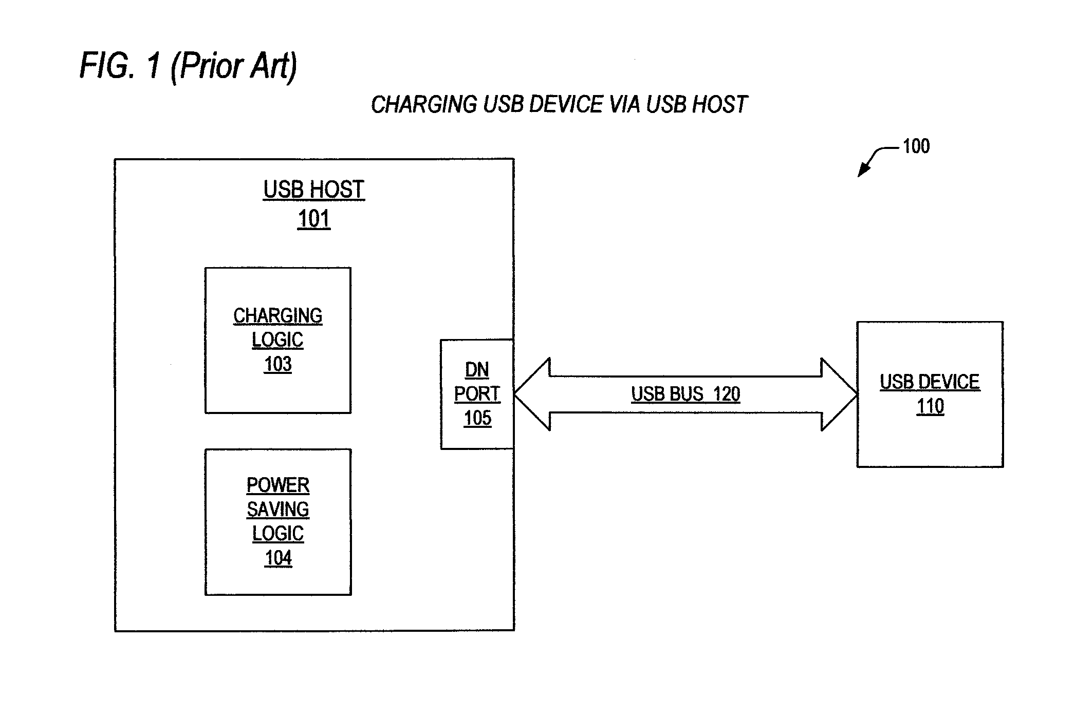
But, as one skilled in the art will appreciate, there are a number of factors that impede optimal charging of USB devices, such as the inability of a USB host or USB hub to charge a corresponding USB device when the USB host is in a power saving state.
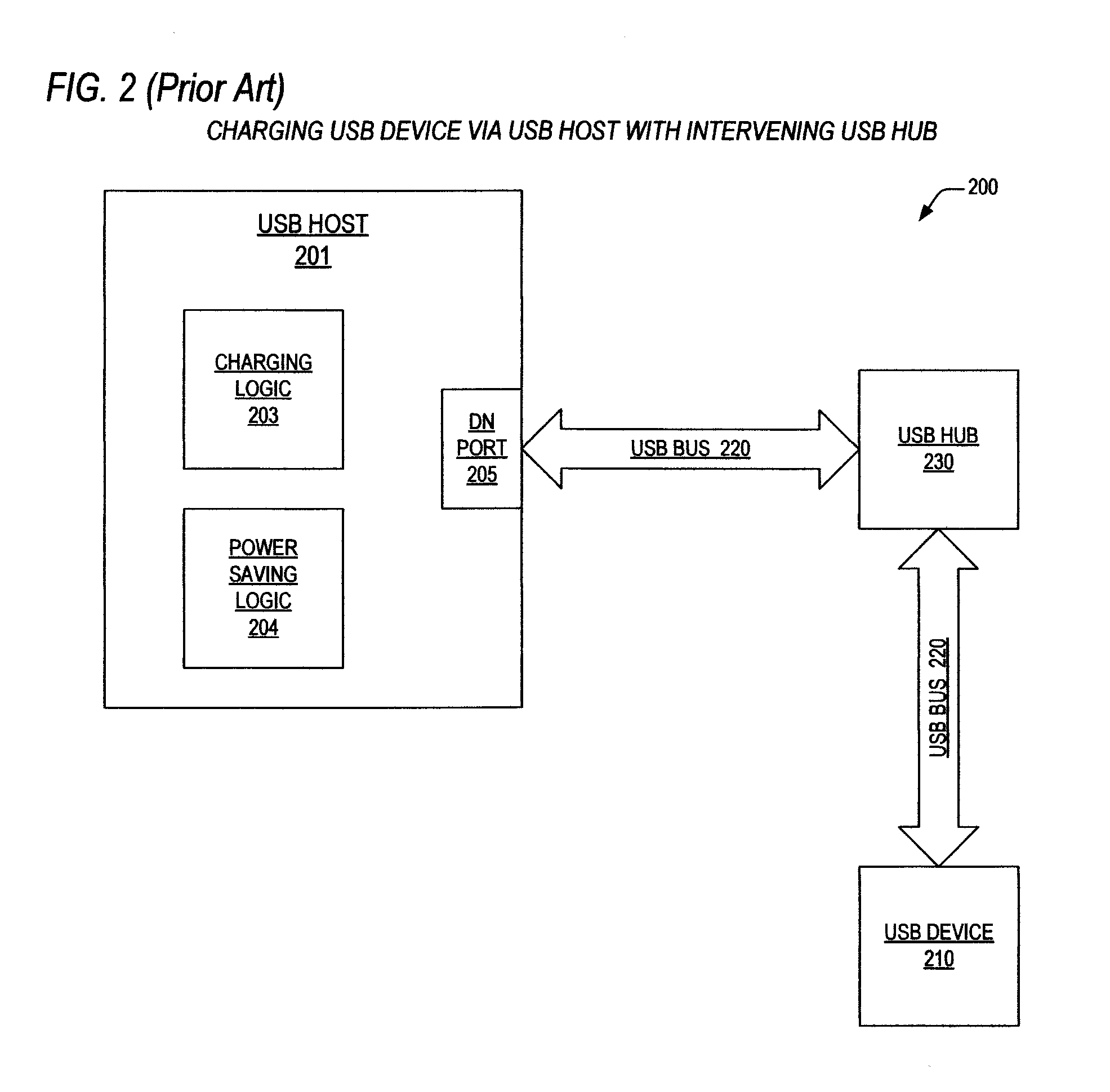
In addition, a present day USB hub is incapable of charging a downstream USB device when the USB hub is disconnected from a USB host.
Finally, because prevailing USB charging specifications only prescribe a limited number of charging modes, most USB devices cannot be charged in an optimal manner.
Furthermore, what is needed is a USB charging module that is disposed in a USB hub, where charging can be affected when a connected USB host is in a power saving state.
Moreover, what is needed is a USB charging technique within a USB host, where charging can be affected when the USB host is in a power saving state.

Method used


Image

  • USB charging module
  • USB charging module
  • USB charging module

Examples


Embodiment Construction

[0024]Exemplary and illustrative embodiments of the invention are described below. In the interest of clarity, not all features of an actual implementation are described in this specification, for those skilled in the art will appreciate that in the development of any such actual embodiment, numerous implementation-specific decisions are made to achieve specific goals, such as compliance with system related and business related constraints, which vary from one implementation to another. Furthermore, it will be appreciated that such a development effort might be complex and time consuming, but would nevertheless be a routine undertaking for those of ordinary skill in the art having the benefit of this disclosure. Various modifications to the preferred embodiment will be apparent to those skilled in the art, and the general principles defined herein may be applied to other embodiments. Therefore, the present invention is not intended to be limited to the particular embodiments shown a...


PUM


Abstract

An apparatus is provided for charging a Universal Serial Bus (USB) device according to an optimal charging mode. The apparatus includes a charging module that is configured to obtain a descriptor from the USB device upon detection of the USB device on a USB bus. The charging module includes one or more descriptor entries disposed in a memory and a controller. The one or more descriptor entries include descriptor data, for matching the descriptor to a specific descriptor entry, and charging data, that specifies the optimal charging mode for the USB device. The controller is coupled to the memory, and is configured to match the descriptor to the specific descriptor entry, and is configured to initiate the optimal charging mode on the USB bus according to the charging data.

Description

BACKGROUND OF THE INVENTION[0001]1. Field of the Invention[0002]This invention relates in general to the field of Universal Serial Bus (USB) devices, and more particularly to USB charging module capable of adaptively charging a USB device.[0003]2. Description of the Related Art[0004]There are literally hundreds of present data devices that communicate with a host computer via the Universal Serial Bus (USB) protocol. And not only does the USB protocol provide for communications between devices, but it also prescribes a number of charging modes, so that a portable device can be recharged as well as communicate over a USB bus.[0005]Consider for example the ubiquitous iPhone®. When coupled to a host computer via a USB bus, the operations of syncing with an iTunes® library can be accomplished, while at the same time recharging the battery within the iPhone.[0006]But, as one skilled in the art will appreciate, there are a number of factors that impede optimal charging of USB devices, such...

Claims


Application Information

Patent Timeline
IPC IPC(8): G06F13/40
CPCG06F13/4068G06F13/4022H02J7/007G06F1/266H02J7/0004G06F13/426H02J7/00036
Inventor LAI, YI-LINCHIU, HAO-HSUANSHIH, TERRANCE
Owner VIA TECH INC
Learn More