

Structure of the Driving Axis of a Puller
a technology of driving axis and puller, which is applied in the direction of metal-working equipment, metal-working equipment, manufacturing tools, etc., can solve the problems of screw bar receiving damage to the positioning element, and achieve the effect of improving the structure of the driving axis of the puller and reducing the maintenance cos
- Summary
- Abstract
- Description
- Claims
- Application Information
AI Technical Summary
Benefits of technology
Problems solved by technology
Method used
Image

Examples
first embodiment
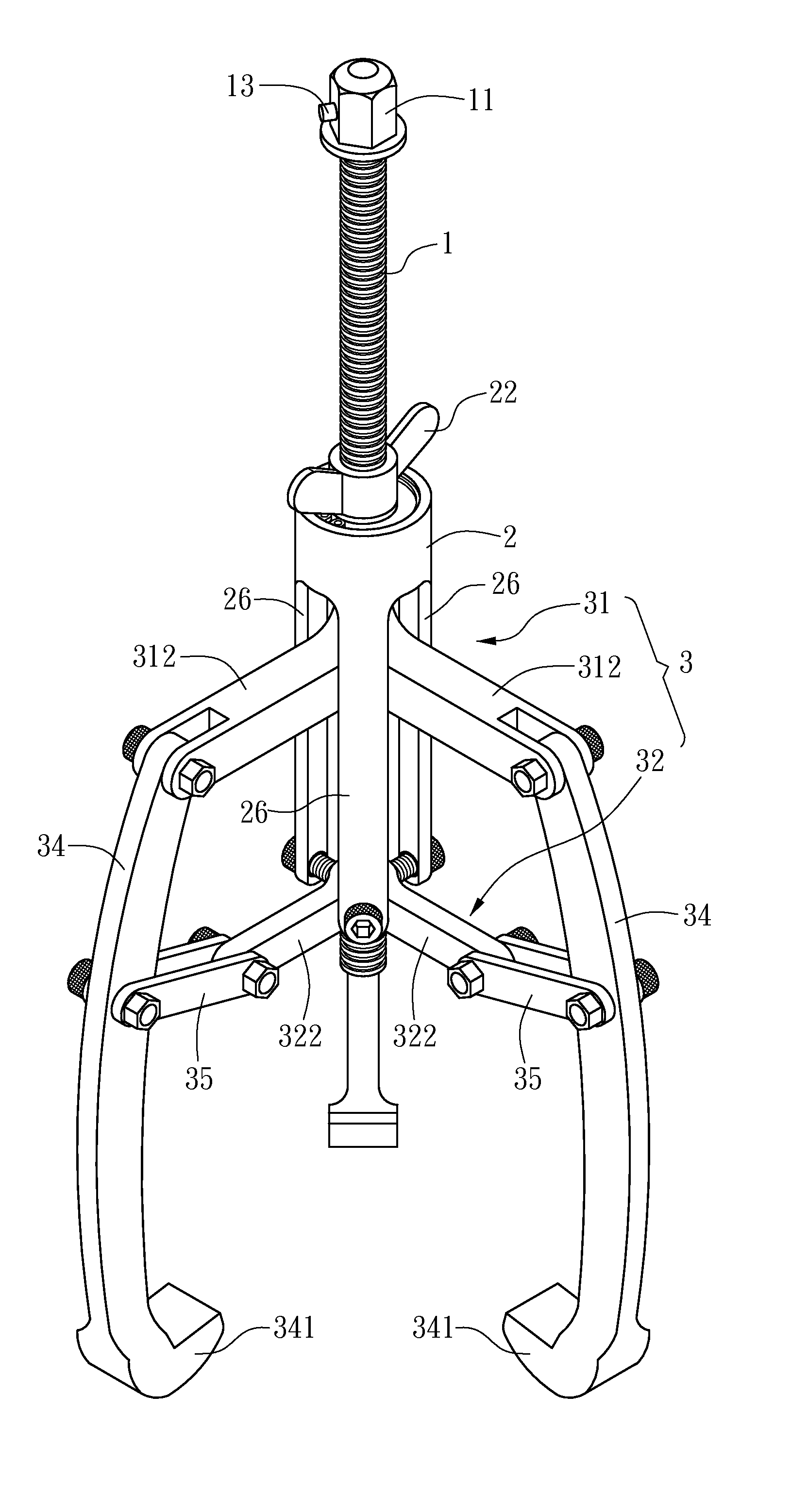
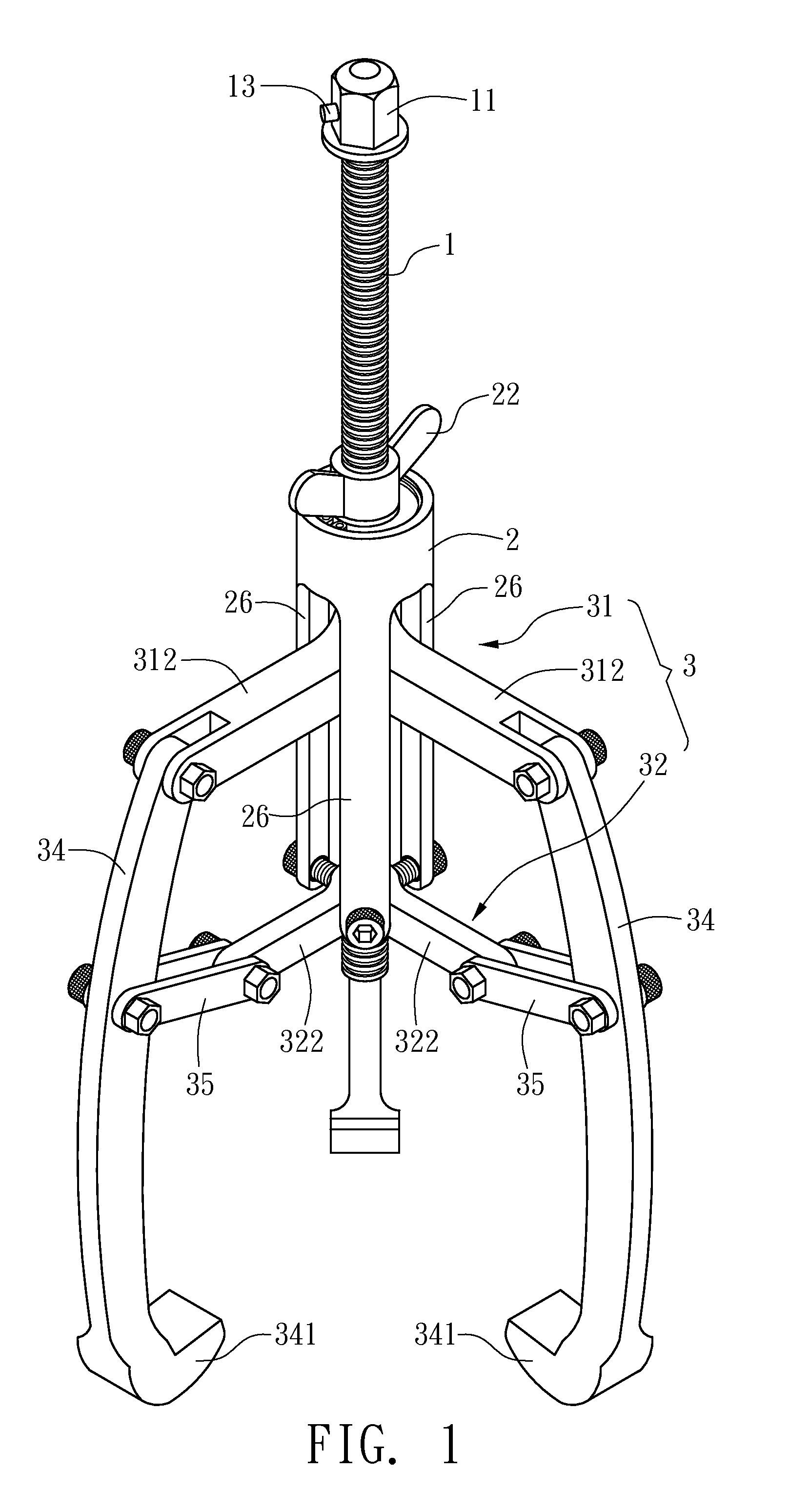
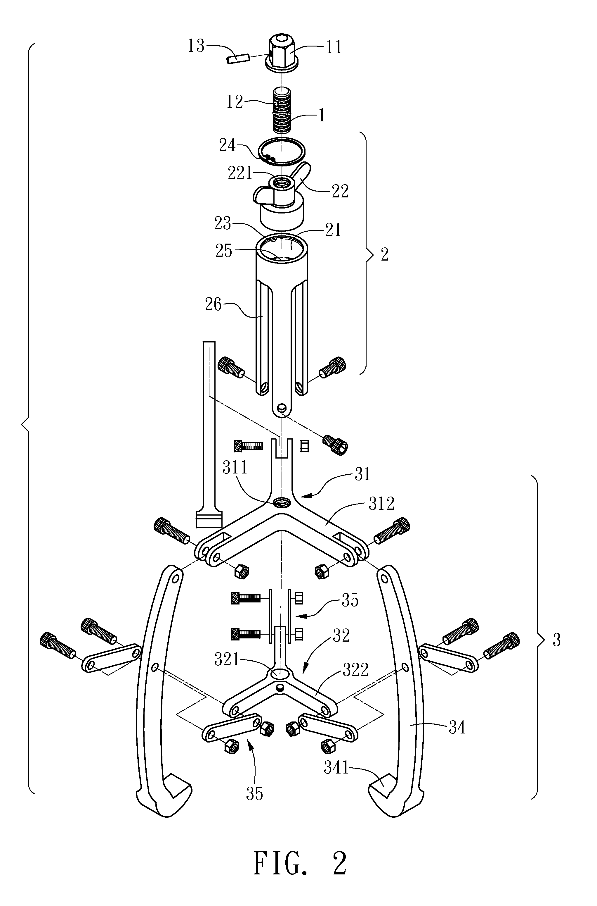
[0022]Please refer to FIGS. 1 to 3 for the improved structure of the driving axis of a puller. The structure includes a screw bar 1, a driving assembly 2, and a driven assembly 3. The screw bar 1 has a top end and a bottom end. As shown in FIGS. 2 and 3, the top end of the screw bar 1 has a rotating element to mount a tool for rotating the screw bar 1. The rotating element 11 has a space 111 corresponding to the top end of the screw bar 1. The side of the space 111 has an inner thread section 112 corresponding to the top end of the screw bar 1, so that the screw bar 1 can be screwed into the space 111. One side of the rotating element 111 has a connecting hole 113 connecting to the space 111. The screw bar 1 has a positioning hole 12 corresponding to the connecting hole 113. A positioning element 13 goes through the connecting hole 113 and gets positioned inside the positioning hole 12. In this embodiment, the positioning element 13 is a pin to fix the rotating element 111 on the to...
second embodiment
[0027]FIG. 7 shows the improved structure of the driving axis of a puller. It differs from the previous embodiment in that the opposite direction of one fixing arm 312B of the screw base 31B is extended with an auxiliary fixing arm 33. The opposite direction of one connecting arm 322B of the connecting base 32B is extended with an auxiliary connecting arm 36. The auxiliary fixing arm 33 and the auxiliary connecting arm 36 and the corresponding fixing arm 312 and connecting arm 322B form a line, respectively. The rest claws 34 can be uncounted from the fixing arms 312 and the action arms 35 and connected with the auxiliary fixing arm 33 and the auxiliary connecting arm 36.
[0028]When this embodiment is in use, the claws 34 can be adopted to fit various environments. When the claws 34 are installed as shown inFIG. 7, it is the same as the first embodiment. In the case of FIG. 8, the three claws can concurrently pull an object, suitable for a more spacious environment. In a narrower spa...
third embodiment
[0029]FIG. 11 shows the invention. This embodiment differs from the first embodiment in that the driven assembly is a connecting base 4. The center of the connecting base 4 has a through hole 41 for the screw bar 1 to penetrate through. The bottom edge of the through hole 41 of the connecting base 4 is extended downward with a screw hole 42 whose inner diameter is greater than that of the through hole 41. The outer part of the connecting base 4 is extended outward with several connecting arms 43. Each of the connecting arms 43 has a guiding part 431 for a pushing bar 44 to be installed thereon in a slideable way.
[0030]The screw bar 1 is provided with an adjusting element 5 for adjusting and positioning the connecting base 4 under the connecting base 4. The outer edge of one end of the adjusting element 5 has an outer thread section 51 for correspondingly connecting to the screw hole 42 of the connecting base 4. The other end is a rotation section 52 for adjustment and rotation. The ...
PUM
| Property | Measurement | Unit |
|---|---|---|
| structure | aaaaa | aaaaa |
| length | aaaaa | aaaaa |
| outer diameter | aaaaa | aaaaa |
Abstract
Description
Claims
Application Information