Pyrotechnic actuator and power cutting tool with safety reaction system having such pyrotechnic actuator

a technology of safety reaction and pyrotechnic actuator, which is applied in the direction of manufacturing tools, metal sawing devices, mechanical devices, etc., can solve the problems of dangerous contact between the blade and an object other than a workpiece, and achieve the effect of low cos

Active Publication Date: 2013-06-20
POWER TOOL INST
View PDF0 Cites 2 Cited by
  • Summary
  • Abstract
  • Description
  • Claims
  • Application Information

AI Technical Summary

Benefits of technology

[0002]In one general aspect, the present disclosure is directed, in part, to a pyrotechnic actuator that can be manufactured with low cost manufacturing processes yet still perform very reliably. In one embodiment, the pyrotechnic actuator can be used in a power cutting tool, such as part of a blade-drop reaction system for a table saw. In such an embodiment, the pyrotechnic actuator can comprise a housing defining a cavity therein, a piston positioned at least partially within the cavity, and an insert-molded unitary assembly positioned within the cavity. The unitary assembly comprises a piston engagement member and a base. A sealed void is defined intermediate the piston engagement member and the base. The unitary assembly comprises a breakable member extending intermediate the piston engagement member and the base and a pyrotechnic initiator positioned at least partially within the base. The pyrotechnic initiator, upon application of a current pulse thereto, is configured to generate a pressurized gas in the sealed void that exerts a force on the piston engagement member and breaks the breakable member, thereby causing the piston engagement member and the piston to move relative to the base and the housing.

Problems solved by technology

Contact between the blade and an object other than a workpiece can be dangerous.

Method used


Image

  • Pyrotechnic actuator and power cutting tool with safety reaction system having such pyrotechnic actuator
  • Pyrotechnic actuator and power cutting tool with safety reaction system having such pyrotechnic actuator
  • Pyrotechnic actuator and power cutting tool with safety reaction system having such pyrotechnic actuator

Examples


Embodiment Construction

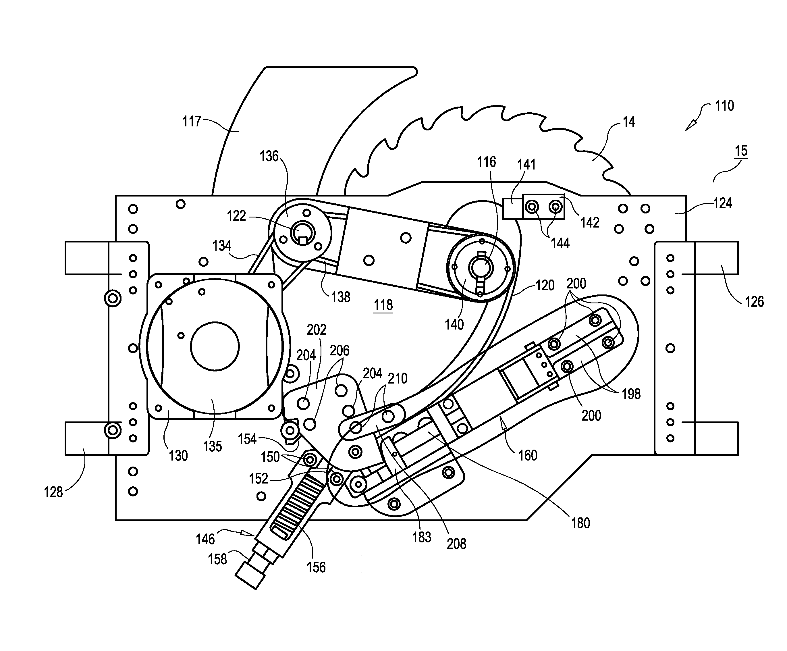
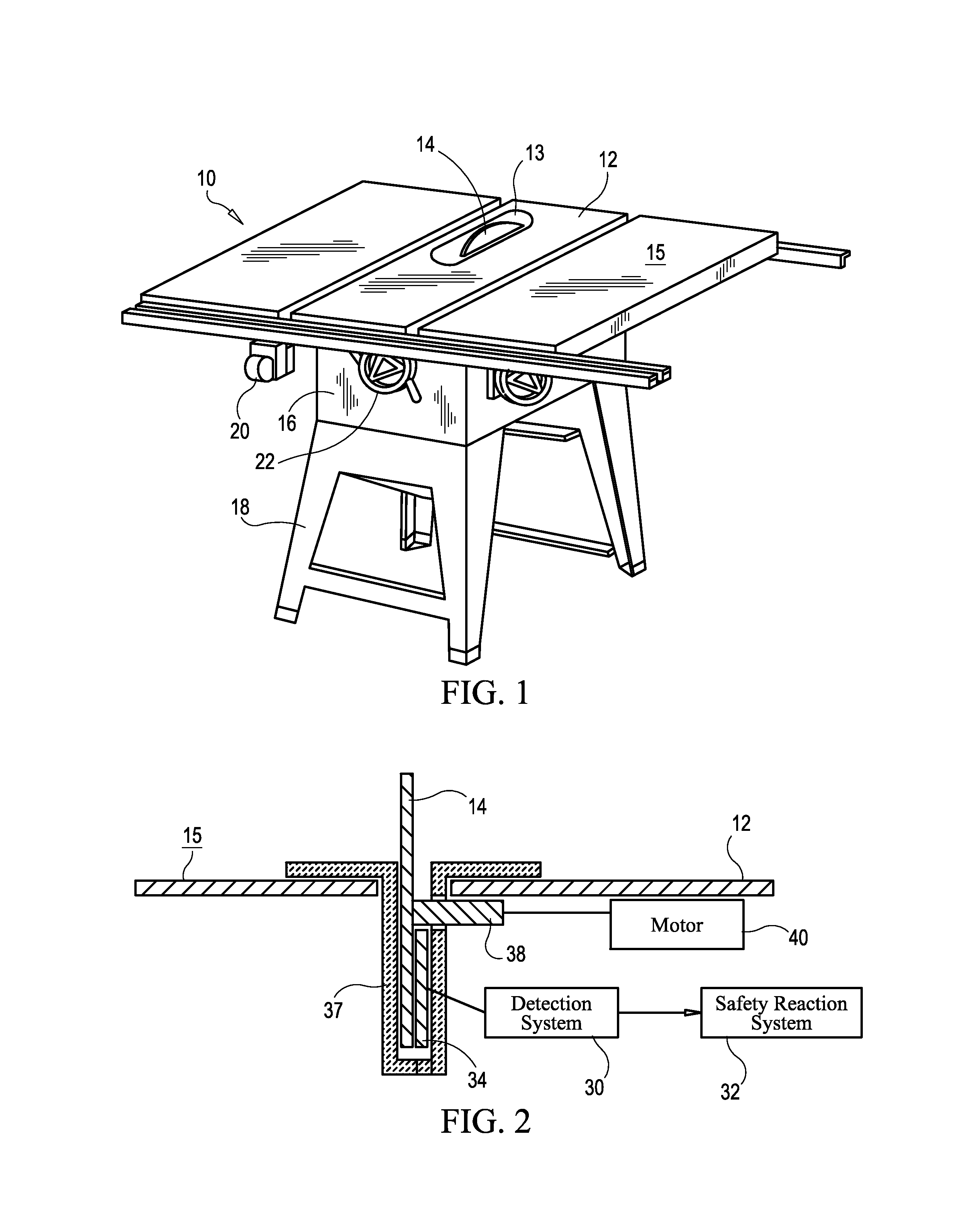
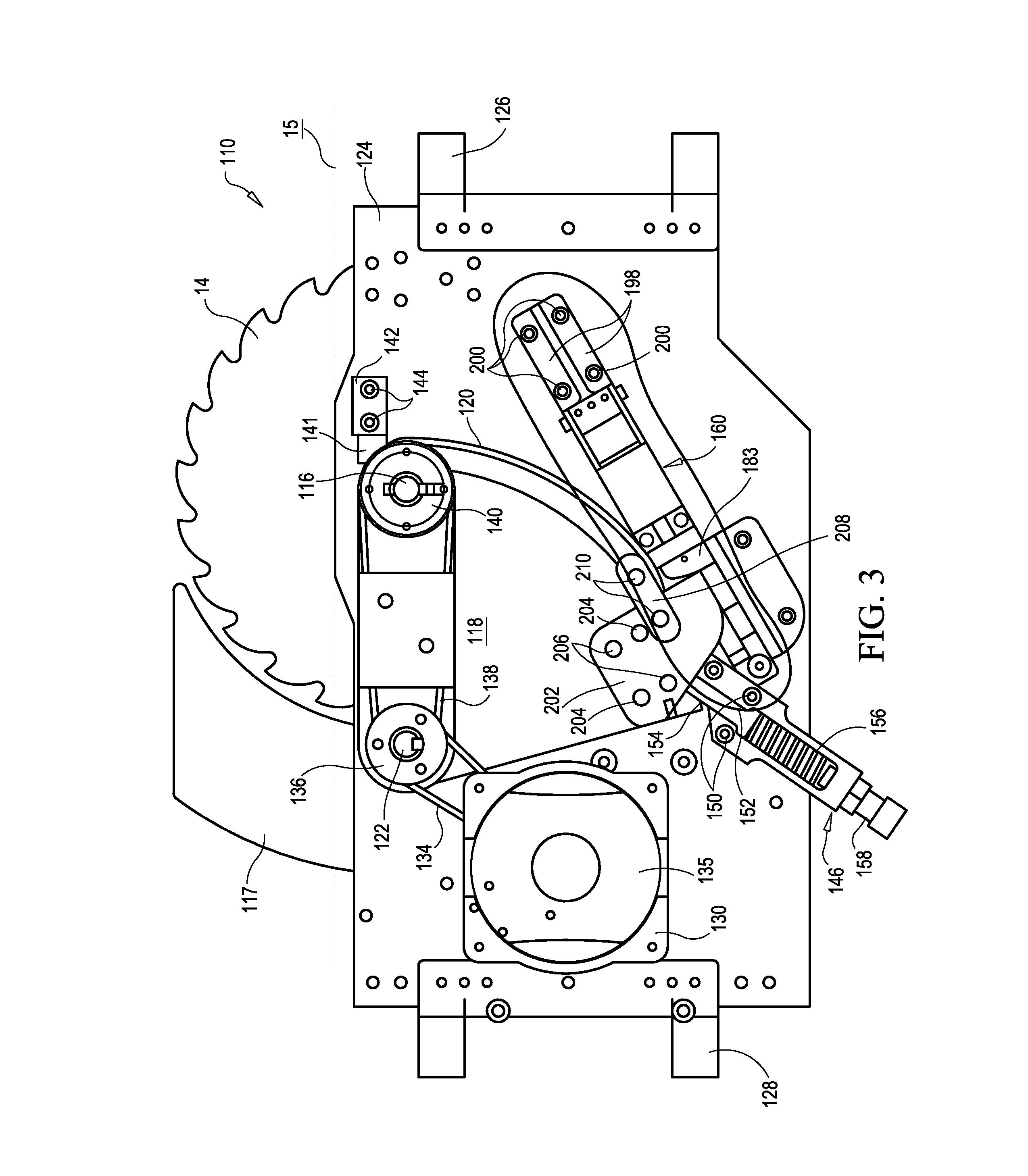
[0022]Various non-limiting embodiments of the present disclosure will now be described to provide an overall understanding of the principles of the structure, function, manufacture, and use of a pyrotechnic actuator and a power cutting tool comprising the pyrotechnic actuator disclosed herein. One or more examples of these non-limiting embodiments are illustrated in the accompanying drawings. It will be appreciated that the pyrotechnic actuators and power cutting tools specifically described herein and illustrated in the accompanying drawings are non-limiting example embodiments and that the scope of the various non-limiting embodiments of the present disclosure are defined solely by the claims. The features illustrated or described in connection with one non-limiting embodiment can be combined with the features of other non-limiting embodiments. Such modifications and variations are intended to be included within the scope of the present disclosure.

[0023]Various embodiments of the ...


PUM

PropertyMeasurementUnit
forceaaaaaaaaaa
metallicaaaaaaaaaa
distanceaaaaaaaaaa

Abstract

A pyrotechnic actuator for a power cutting tool is disclosed. The pyrotechnic actuator comprises a housing defining a cavity therein, a piston positioned at least partially within the cavity, and an insert-molded unitary assembly positioned within the cavity. The unitary assembly comprises a piston engagement member and a base. A sealed void is defined intermediate the piston engagement member and the base. The unitary assembly comprises a breakable member extending intermediate the piston engagement member and the base and a pyrotechnic initiator positioned at least partially within the base. The pyrotechnic initiator, upon application of a current pulse thereto, is configured to generate a pressurized gas in the sealed void that exerts a force on the piston engagement member and breaks the breakable member thereby causing the piston engagement member and the piston to move relative to the base and the housing.

Description

BACKGROUND[0001]Many types of power tools have exposed blades, such as table saws and other power cutting tools. Contact between the blade and an object other than a workpiece can be dangerous. Safety systems to mitigate potentially dangerous conditions are continually being developed. Some such safety systems include a blade-drop mechanism that drops the blade below the working surface of the power tool when contact or near-contact with a foreign object is detected, for example. In some instances, such blade-drop mechanisms are actuated by a pyrotechnic actuator. Improved pyrotechnic actuators for these and other applications are needed.SUMMARY[0002]In one general aspect, the present disclosure is directed, in part, to a pyrotechnic actuator that can be manufactured with low cost manufacturing processes yet still perform very reliably. In one embodiment, the pyrotechnic actuator can be used in a power cutting tool, such as part of a blade-drop reaction system for a table saw. In su...

Claims


Application Information

Patent Timeline
Patent Type & Authority Applications(United States)
IPC IPC(8): B26D7/22B23D45/06F42B99/00
CPCB27G19/02F42B3/006F15B15/19H01H39/006Y10T83/626Y10T83/773
Inventor KAJITA, EISHIAVETISIAN, VAHANTIRMIZI, ABRAR
Owner POWER TOOL INST
Why Eureka
Try Eureka