Device and method for dispensing a liquid product that is to be sprayed onto a surface

a liquid product and surface technology, applied in the direction of liquid fertiliser regulation system, insect catchers and killers, agriculture, etc., can solve the problems of non-planar topography and pressure differences, and achieve the effect of achieving corrective maintenance more quickly and precisely

Active Publication Date: 2013-06-20
EXCEL IND INC
View PDF6 Cites 28 Cited by
  • Summary
  • Abstract
  • Description
  • Claims
  • Application Information

AI Technical Summary

Benefits of technology

[0072]Thus, the operator performs corrective maintenance more quickly and precisely. This pressure difference may be set at a significant value. Two clogs may arise: if a filter mounted on the duct is clogged, then the pressure inside the target duct decreases abnormally relative to that of its adjacent ducts. Conversely, if nozzles clog, the pressure inside the target channel increases abnormally relative to that of its adjacent ducts. In both cases, a signal identifying the target duct informs the operator of the clog. This method is implemented both with a bar having serial ducts and with a bar having parallel ducts.

Problems solved by technology

However, many agricultural fields have a non-planar topography, with raised areas such as a slope or banking, a peak, a thalweg, etc.
However, the altimetric differences between the nozzles create pressure differences that depend on the height of the column of liquid separating them and the density of the liquid.
The flow rate of the nozzle being proportional to the square root of the pressure, the flow rate of liquid product differs on each nozzle, such that the liquid product is not uniformly sprayed on each surface unit.
Such a flow rate difference causes a major irregularity (18% in this example) in the treatment of the agricultural field between two consecutive shared passages, and therefore growth differences between adjacent plants of less than 1 m. Furthermore, certain standards require a maximum gap of 10% between the volumes of liquid product that are sprayed onto surface units during a same spraying operation.

Method used


Image

  • Device and method for dispensing a liquid product that is to be sprayed onto a surface
  • Device and method for dispensing a liquid product that is to be sprayed onto a surface
  • Device and method for dispensing a liquid product that is to be sprayed onto a surface

Examples


second embodiment

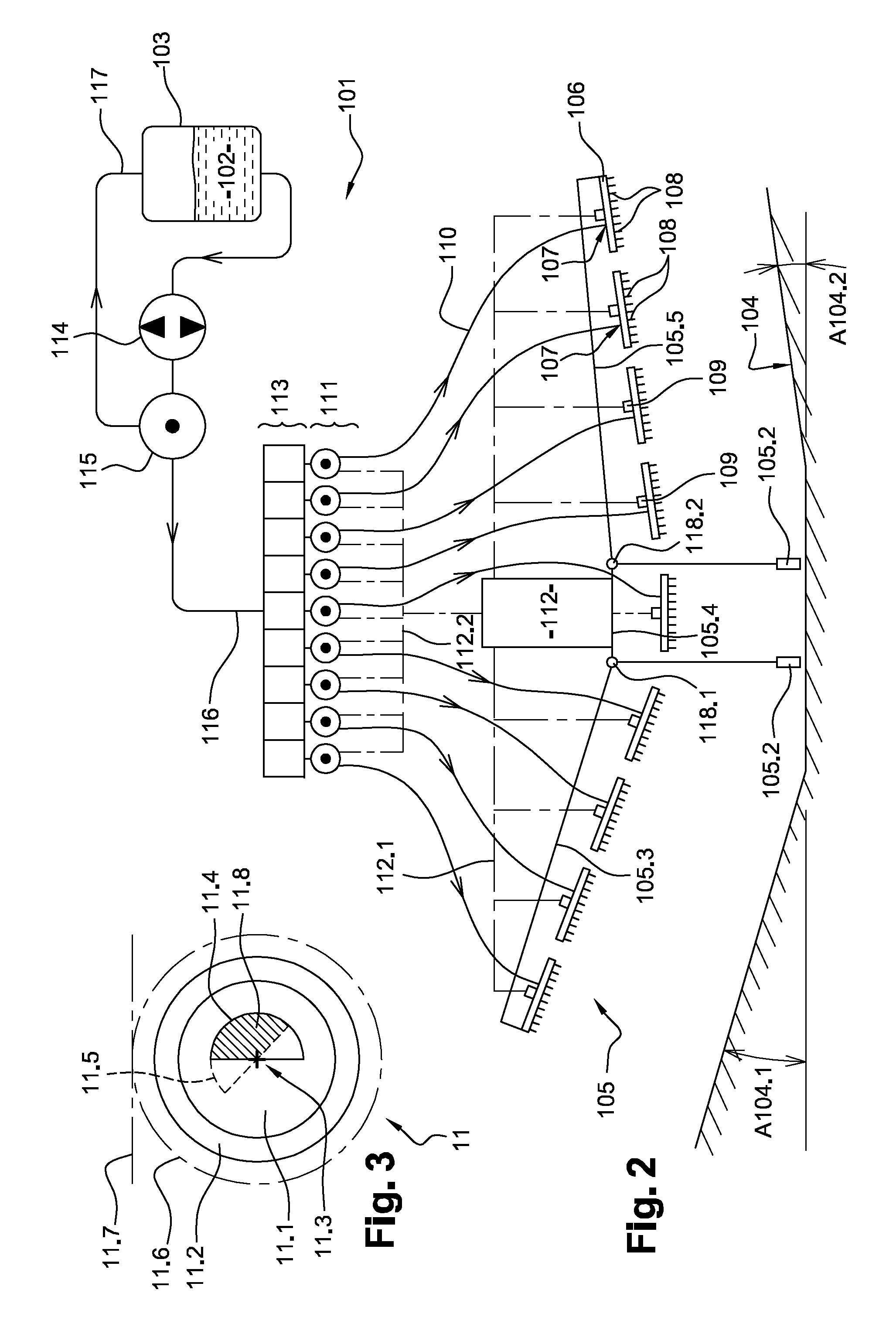
[0114]FIG. 2 illustrates a device 101 according to the invention. As far as the device 101 is similar to the device 1, the description of the device 1 provided above relative to FIG. 1 can be transposed to the device 101, with the exception of the differences hereafter described. An element of the device 101 that is similar or corresponds, in terms of structure or function, to an element of the device 1 bears the same reference number increased by 100.

[0115]One thus defines a liquid product 102, a reservoir 103, a surface 104, a bar 105 with wheels 105.2, ducts 106, inlets 107, nozzles 108, supply ducts 110, members 111, a control unit 112, cutoff valves 113, a pump 114, a bypass valve 115, a shared conduit 116 and a return conduit 117.

[0116]The device 101 differs from the device 1, because the chassis of the bar 105 has a variable geometry, i.e., it comprises a central frame 105.4 and two moving arms 105.3 and 105.5, as well as connecting means 118.1 and 118.2 between the central f...

fourth embodiment

[0140]FIG. 5 illustrates a device 301 according to the invention. As far as the device 301 is similar to the device 201, the description of the device 201 provided above relative to FIG. 4 can be transposed to the device 301, with the exception of the differences hereafter described. An element of the device 301 that is similar or corresponds, in terms of structure or function, to an element of the device 201 bears the same reference number increased by 300.

[0141]One thus defines a liquid product 302, a reservoir 303, a surface 304 with an angle A304, a bar 305, ducts 306, inlets 307, nozzles 308, supply conduits 310, members 311, a control unit 312, a pump 314, a bypass valve 315 and a return conduit 317.

[0142]The device 301 differs from the device 201 in that the bar 305 includes restrictors 311.1 and 311.2 arranged at each end of the bar 305, instead of cutoff valves 213. Each member 311.1 or 311.2 is driven by the control unit 312. Each member 311.1 or 311.2 is formed by a flow ...


PUM


Abstract

The device according to the invention comprises a bar that includes several consecutive ducts with at least one inlet connected to a source of the liquid product and outlets communicating with nozzles. The device further comprises several sensors for measuring a physical property making it possible to determine a pressure difference between ducts or a pressure in one respective duct, several members designed to vary the pressures inside respective ducts, as well as at least one control unit estimating the pressure differences between ducts and driving the members to reduce those pressure differences or equalize those pressures. This device thus limits the pressure differences, and therefore flow differences, of the liquid product between the nozzles, in particular between the ends of very long bars moving over significant bankings.

Description

TECHNICAL FIELD[0001]The present invention relates to a device and a method for dispensing a liquid product to be sprayed on a surface, such as an agricultural field.BRIEF DESCRIPTION OF RELATED ART[0002]The present invention is applicable in the agricultural field in order to spray a field with a liquid phytosanitary product, such as a fertilizer or a biocide of the herbicide, insecticide, fungicide, or other type.[0003]A dispensing device of the prior art comprises a conventional spraybar or bar, which comprises several consecutive ducts, each forming a longitudinal section of the bar and having a supply inlet and outlets connected to nozzles adapted to spray the liquid product on a target, in general on the ground or plants, approximately 70 cm away. The bar is supplied with liquid product by a pump, which suctions liquid product from a source and discharges it into several supply conduits respectively connected to the inlets of the ducts. Generally, the pump is coupled to a bypa...

Claims


Application Information

Patent Timeline
Patent Type & Authority Applications(United States)
IPC IPC(8): A01C23/00B05B12/00
CPCA01M7/0042A01C23/007A01M7/0089B05B12/006A01C23/047
Inventor BALLU, PATRICK JEAN MARIE
Owner EXCEL IND INC
Why Eureka
Try Eureka