Printing method and printing device
a printing device and printing method technology, applied in printing, dyeing process, inks, etc., can solve the problems of large effort required to perform, and achieve the effect of easy dyeing
- Summary
- Abstract
- Description
- Claims
- Application Information
AI Technical Summary
Benefits of technology
Problems solved by technology
Method used
Image

Examples
embodiment 1
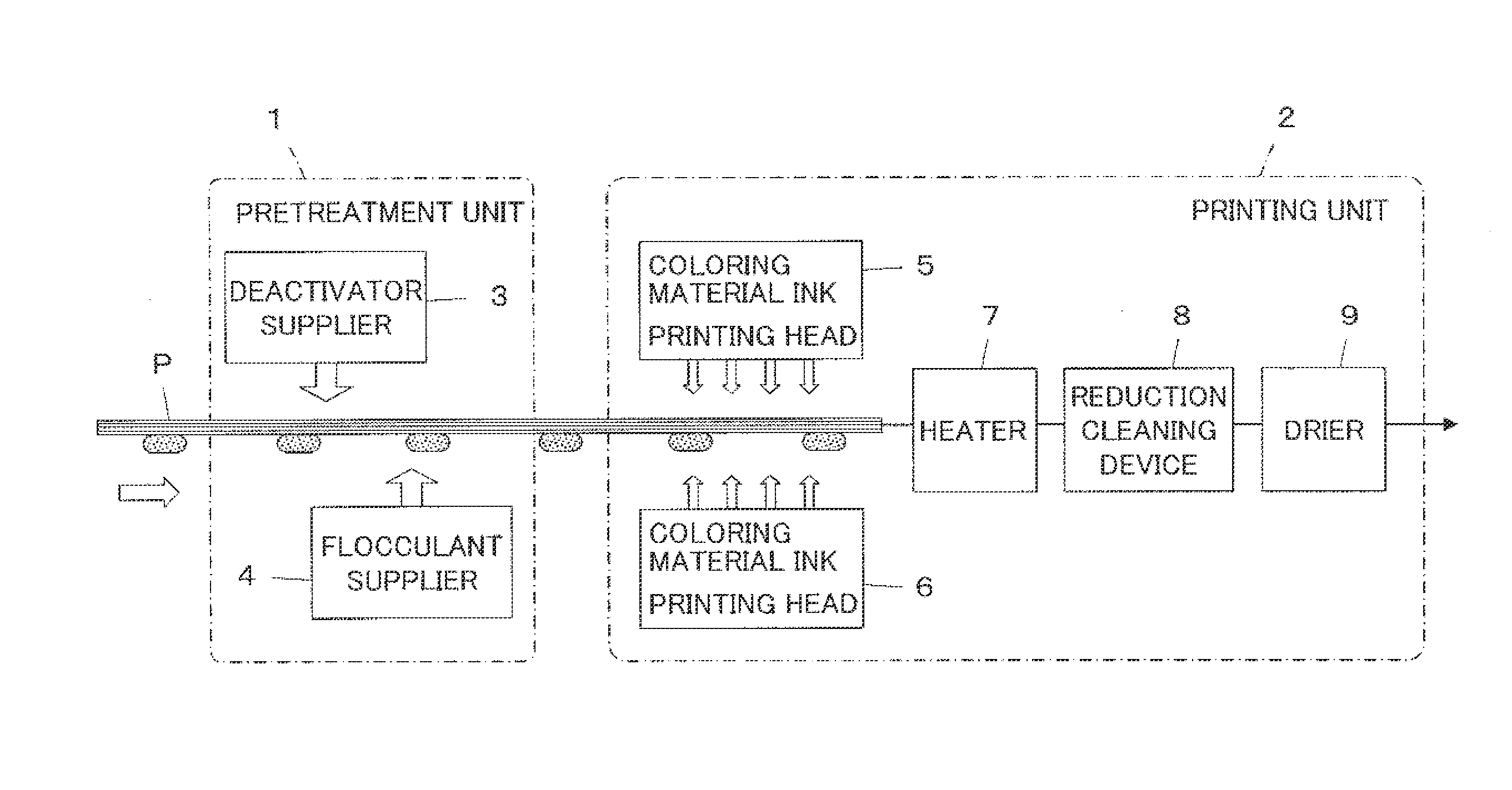
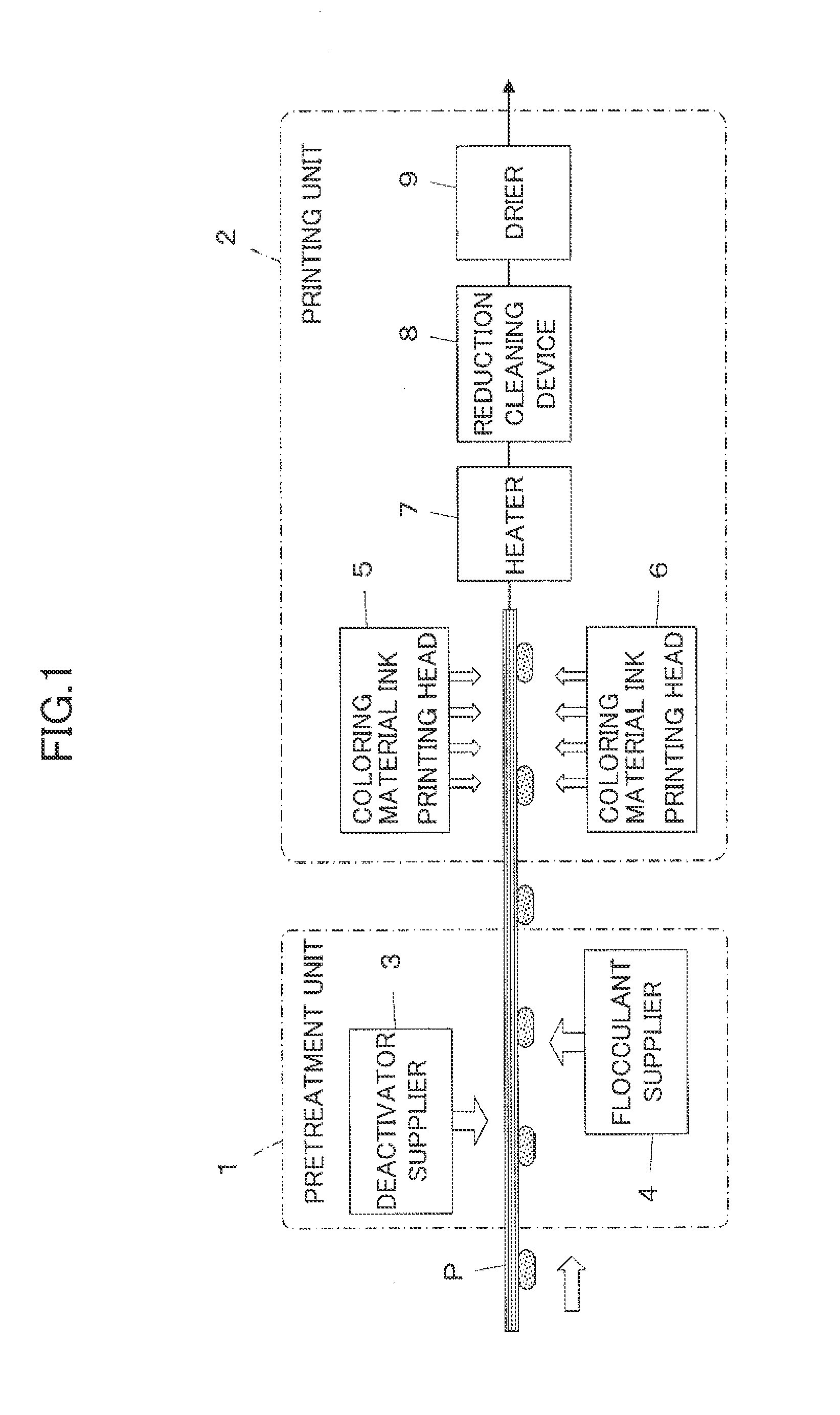
[0049]FIG. 1 illustrates a configuration of a printing device according to Embodiment 1 of the present invention. The printing device comprises a pretreatment unit 1 adapted to perform a pretreatment on a printing medium P and a printing unit 2 adapted to perform printing on the printing medium P.
[0050]The printing medium P comprises, for example, a base texture of polyester fibers having a great capillary force and hence tending to readily retain ink and fastener snaps (snaps) made of polyester that have a smaller capillary force than the base texture and tending to retain less ink than the base texture. The capillary force herein denotes an ability of each region of the printing medium P to retain ink such that a region having a great capillary force is capable of drawing ink by capillary force from neighboring regions having relatively smaller capillary forces, whereas a region having a small capillary force is incapable of holding ink with an attractive force from neighboring re...
embodiment 2
[0077]The printing medium P used in Embodiment 1 may be a resin sheet material containing regions having different capillary forces.
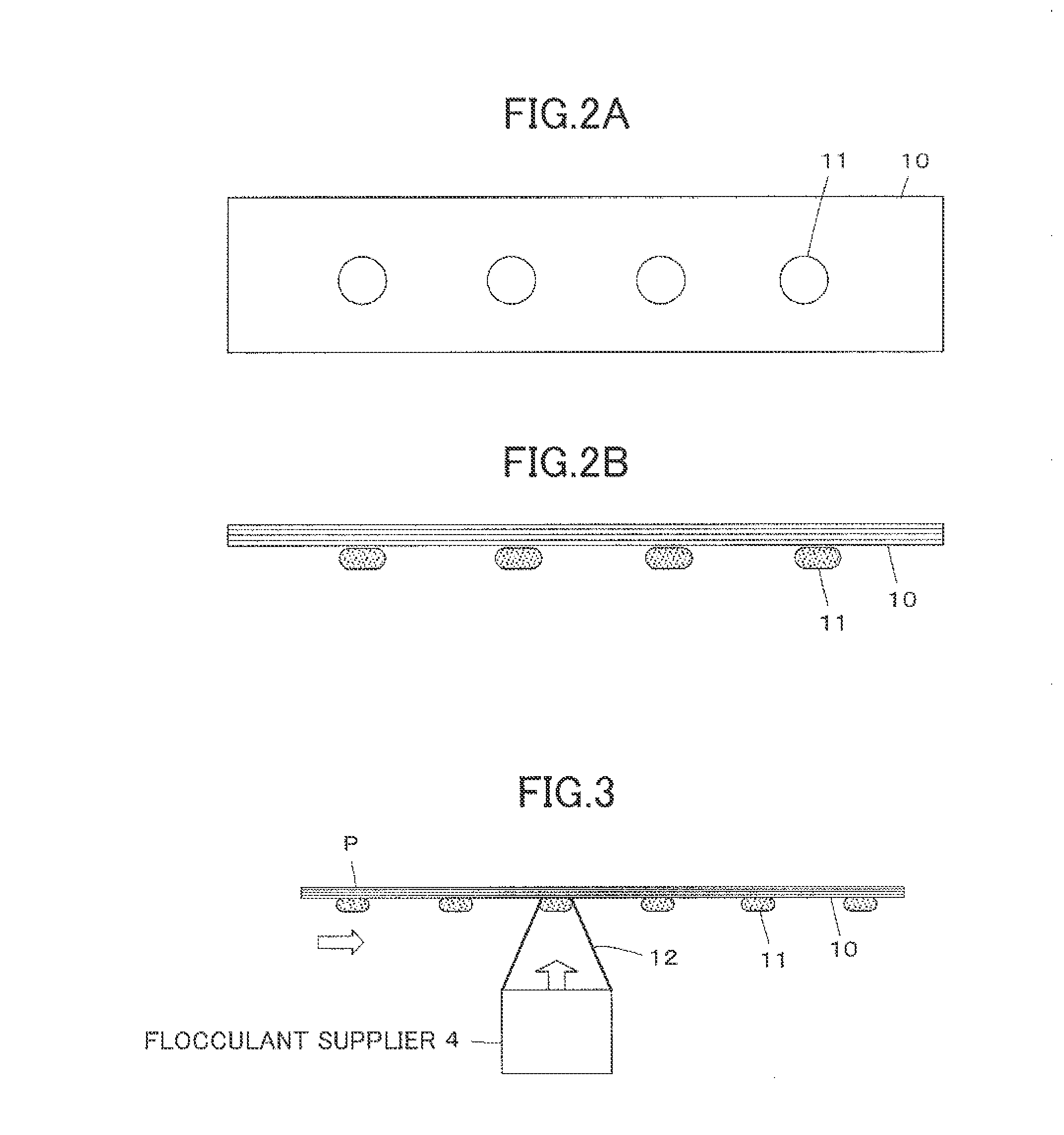
[0078]An example thereof is the printing medium P having pits 21 formed in a resin sheet as illustrated in FIG. 5. Formation of the pits 21 creates a difference in capillary force between the pits 21 and neighboring projections 22, so that ink supplied to the projections 22 tends to move to neighboring pits 21. Thus, the printing medium P comprises the pits 21 having a great capillary force and the projections 22 having a small capillary force. The edge portions on both sides of each pit 21 as seen in the drawing have a greater capillary force than the central portion of the pit and tend to gather ink droplets. First, the flocculant supplier 4 supplies the flocculant to the printing medium P. Because the flocculant is supplied in a droplet size that is sufficiently smaller than the capillary force length, use may be made of an ultrasonic nebulizer, for ...
embodiment 3
[0085]The printing medium P used in Embodiment 1 may be a raised fabric comprising a base texture having a great capillary force and a raised texture having a small capillary force as illustrated in FIG. 8. First, the deactivator supplier 3 supplies the deactivator to the base texture from the reverse surface side of the printing medium P. The supplied deactivator penetrates through to the front surface of the base texture. Next, the flocculant supplier 4 supplies a mist of flocculant from the front side of the printing medium P. Because the flocculant supplier 4 supplies the flocculant with the dimensions and amount adjusted, the flocculant is supplied to the raised fabric in such size and at such intervals that the droplets thereof do not unite.
[0086]Subsequently, the printing heads 5 and 6 shoot ink droplets at the printing medium P. The ink droplets ejected from the printing head 5 are supplied to the base texture from the reverse surface side of the printing medium P and penetr...
PUM
| Property | Measurement | Unit |
|---|---|---|
| Force | aaaaa | aaaaa |
| Viscosity | aaaaa | aaaaa |
| Size | aaaaa | aaaaa |
Abstract
Description
Claims
Application Information
 - R&D
- Intellectual Property
- Life Sciences
- Materials
- Tech Scout
- Unparalleled Data Quality
- Higher Quality Content
- 60% Fewer Hallucinations
Browse by: Latest US Patents, China's latest patents, Technical Efficacy Thesaurus, Application Domain, Technology Topic, Popular Technical Reports.
© 2025 PatSnap. All rights reserved.Legal|Privacy policy|Modern Slavery Act Transparency Statement|Sitemap|About US| Contact US: help@patsnap.com