Device for measuring three dimensional shape

Active Publication Date: 2013-06-20
CKD
View PDF9 Cites 5 Cited by
  • Summary
  • Abstract
  • Description
  • Claims
  • Application Information

AI Technical Summary

Benefits of technology

[0026]It is thus possible to reduce the time interval required until acquisition of all the required image data for conduction of three dimensional measurement within a certain measurement subject range.
[0027]For example, within a certain measurement subject range, assuming a total of 8 imaging operations (4 images each for each light pattern, using two light patterns), assuming that the time interval required for a single image is 2 msec, and assuming that the required time interval per shifting of the grating is 20 msec, then, the time required for the present aspect until completion of all processing within the certain measurement subject range becomes 96 msec (i.e., (first light pattern irradiation time of 20 msec+second light pattern irradiation time of 20 msec)×4 times=a total of 96 msec). That is, it becomes possible to reduce the time by 64 msec (40%) in comparison to the configuration of the aforementioned Patent Document 1 that separately performs shifting or the like of the first grating and the second grati

Problems solved by technology

However, when using only a single aforementioned irradiation unit, shadowed parts may occur where the light pattern is not irradiated on t

Method used


Image

  • Device for measuring three dimensional shape
  • Device for measuring three dimensional shape
  • Device for measuring three dimensional shape

Examples


Embodiment Construction

[0045]One or more embodiments of the claimed invention will be explained below while referring to figures.

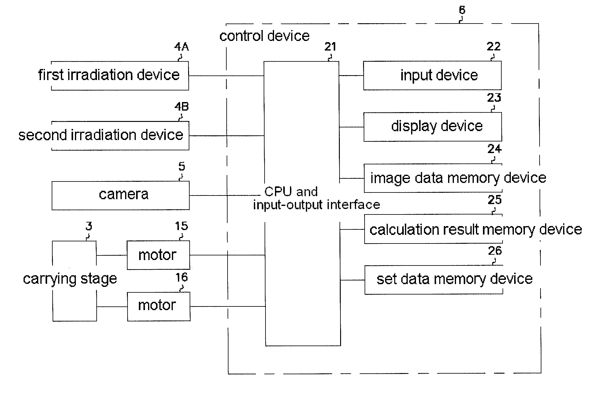
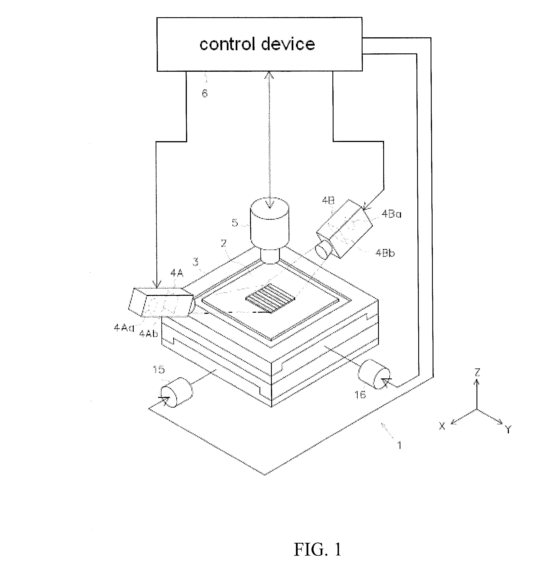
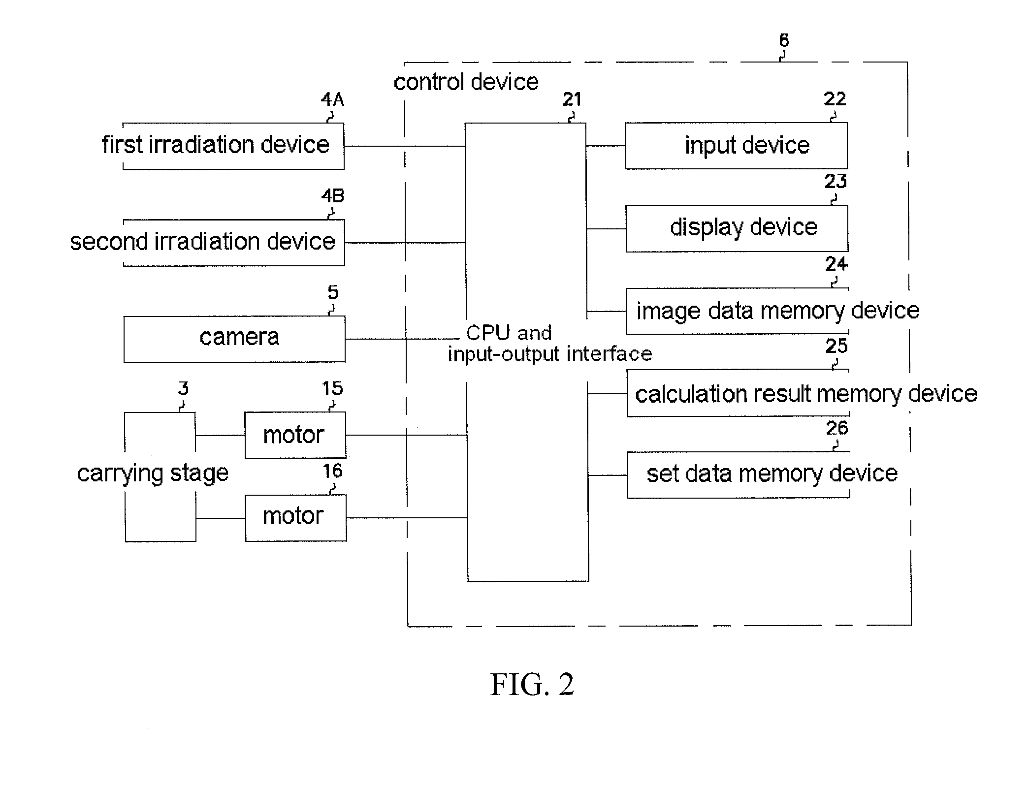
[0046]FIG. 1 is a rough structural drawing showing schematically a board inspection device 1 equipped with the device for measuring three dimensional shape of the present embodiment. As shown in this figure, the board inspection apparatus 1 is equipped with a carrying stage 3 for carrying a printed board 2 as an object to be measured produced by printing cream solder as the measurement subject, two irradiation devices (i.e., first irradiation device 4A as the first irradiation unit, and second irradiation device 4B as the second irradiation unit) for irradiation of a certain light pattern from above at a tilted angle upon the surface of the printed board 2, a camera 5 as an imaging unit for imaging the irradiated part of the printed board 2, and a control device 6 for execution of various types of control within the board inspection apparatus 1 and for image processing and calcu...


PUM


Abstract

A device for measuring three dimensional shape includes a first irradiation unit, a first grating control unit, a second irradiation unit, a second grating control unit, an imaging unit, and an image processing unit. After performance of a first imaging operation as imaging processing of a single operation among a multiplicity of imaging operations performed by irradiation of said first light pattern of multiply varied phases, a second imaging operation is performed as imaging processing of a single operation among a multiplicity of imaging operations performed by irradiation of said second light pattern of multiply varied phases. After completion of the first imaging operation and the second imaging operation, shifting or switching operation of the first grating and the second grating is performed simultaneously.

Description

CROSS-REFERENCE TO RELATED APPLICATIONS[0001]This application claims priority to Japanese Patent Application No. 2011-273984 filed on Dec. 15, 2011 in Japan.BACKGROUND OF INVENTION[0002]1. Field of the Invention[0003]The present invention relates to a device for measuring three dimensional shape.[0004]2. Background Art[0005]Generally, when electronic components are mounted on a printed board, firstly cream solder is printed at certain positions on the electrode pattern. Thereafter, the electronic components are temporarily fixed to the printed board by use of viscosity of the cream solder. Thereafter, the aforementioned printed board is conveyed to a reflow furnace, the printed board is subjected to a certain reflow step, and soldering is performed. In recent years, inspection of the printed state of the cream solder has been required at a stage prior the printed board being conveyed to the reflow furnace. A device for measuring three dimensional shape is used during this inspection...

Claims


Application Information

Patent Timeline
IPC IPC(8): H04N13/02
CPCG01B11/2509G01B11/2513G06T2207/30152G06T2207/10152G06T2207/30141G06T7/0057G06T7/521
Inventor ISHIGAKI, HIROYUKI
Owner CKD
Why Eureka
Try Eureka