Core and optical waveguide

Inactive Publication Date: 2013-06-20
ELECTRONICS & TELECOMM RES INST
View PDF3 Cites 1 Cited by
  • Summary
  • Abstract
  • Description
  • Claims
  • Application Information

AI Technical Summary

Benefits of technology

The patent describes a new design for an optical waveguide that includes a core with a taper structure. The taper structure decreases in light-receiving width as it goes from one end to the other, and includes a first lightwave propagation portion, a first lightwave discontinuous portion, a first taper structure portion, a second lightwave propagation portion, a second lightwave discontinuous portion, and a second taper structure portion. The first taper structure portion decreases in light-receiving width as it goes from the first lightwave propagation portion to the first lightwave discontinuous portion, and the second taper structure portion decreases in light-receiving width as it goes from the second lightwave propagation portion to the second lightwave discontinuous portion. The core may also include a half-wavelength polarizer to convert impinging transverse electric (TE) polarization to transverse magnetic (TM) polarization. The optical waveguide may be formed on a silica glass substrate, a polymer substrate, or a single-crystalline substrate. The technical effect of this design is to improve the coupling of light between the waveguide and external devices, and to reduce the loss of light during transmission.

Problems solved by technology

Various optical circuits for performing different functions may be monolithically integrated on the same substrate.
However, a discontinuous optical waveguide inevitably exists on a substrate when there is a need to integrate an optical device such as a polarization rotator that has difficulty in being implemented only using an optical waveguide.
Optical power loss increases at the discontinuous portion.

Method used


Image

  • Core and optical waveguide
  • Core and optical waveguide
  • Core and optical waveguide

Examples


Embodiment Construction

[0027]The advantages and features of the inventive concept and methods of achieving them will be apparent from the following exemplary embodiments that will be described in more detail with reference to the accompanying drawings. It should be noted, however, that the inventive concept is not limited to the following exemplary embodiments, and may be implemented in various forms. Accordingly, the exemplary embodiments are provided only to disclose examples of the inventive concept and to let those skilled in the art understand the nature of the inventive concept.

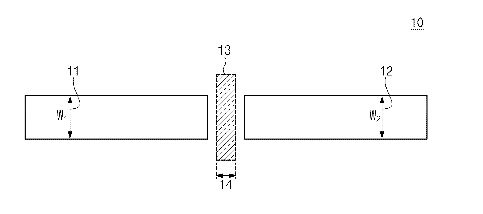
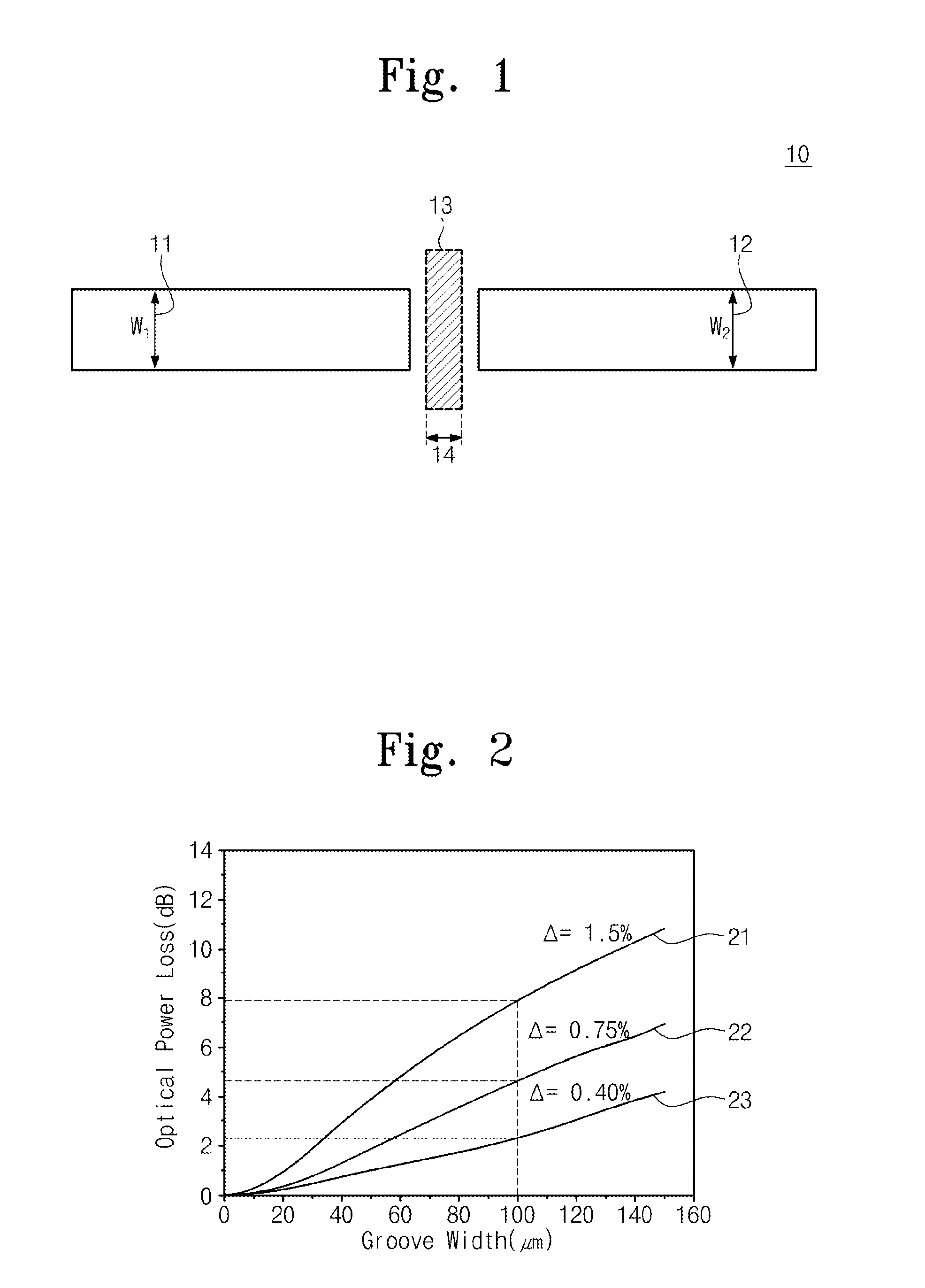
[0028]Reference is made to FIG. 1, which illustrates a typical core 10. The typical core 10 includes a half-wavelength polarizer 13 at a discontinuous portion. Widths 11 and 12 of the core 10 are W1 and W2, respectively, which are constant. A groove is formed in a length direction of the core 10, i.e., a direction perpendicular to an optical axis direction. And the half-wavelength polarizer 13 is included in the groove. Howev...


PUM


Abstract

Provided is a core which reduces optic splice loss between discontinuous optical waveguides. The core includes a first waveguide propagation portion having first light-receiving width, a first lightwave discontinuous portion having second light-receiving width, a first taper structure portion having both ends connected to the first lightwave propagation portion and to the first lightwave discontinuous portion, respectively and decreasing in light-receiving width as it goes from the first lightwave propagation portion to the first lightwave discontinuous portion, a second lightwave propagation portion having third light-receiving width, a second lightwave discontinuous portion having fourth light-receiving width, and a second taper structure portion having both ends connected to the second lightwave propagation portion and to the second lightwave discontinuous portion, respectively and decreasing in light-receiving width as it goes from the second lightwave propagation portion to the second lightwave discontinuous portion.

Description

CROSS-REFERENCE TO RELATED APPLICATIONS[0001]This US non-provisional patent application claims priority under 35 USC §119 to Korean Patent Application No. 10-2011-0134353, filed on Dec. 14, 2011, the entirety of which is hereby incorporated by reference.BACKGROUND OF THE INVENTION[0002]The present general inventive concept relates to cores and optical waveguides and, more particularly, to a core and an optical waveguide which reduce optic splice loss.[0003]In order for lightwaves to propagate in a constrained state by total internal reflection principle, without radiating to the outside, there is required a structure in which a specific dielectric substance is surrounded by another dielectric substance with a relatively low refractive index. A lightwave propagation path in which the structure is maintained can be referred to as an optical waveguide, and an optical fiber for communication is a representative example to which the optical waveguide is applied. In an optical waveguide, ...

Claims


Application Information

Patent Timeline
IPC IPC(8): G02B6/26G02B6/00
CPCG02B6/126G02B6/1228G02B6/122
Inventor KIM, DUK JUNKIM, JONG-HOICHOE, JOONG-SEONYOUN, CHUN JUCHOI, KWANG-SEONGKWON, YONG-HWANNAM, EUN SOO
Owner ELECTRONICS & TELECOMM RES INST
Why Eureka
Try Eureka