
Light emitting display apparatus

Pending Publication Date: 2022-03-31
LG DISPLAY CO LTD
View PDF3 Cites 0 Cited by
  • Summary
  • Abstract
  • Description
  • Claims
  • Application Information

AI Technical Summary

Benefits of technology

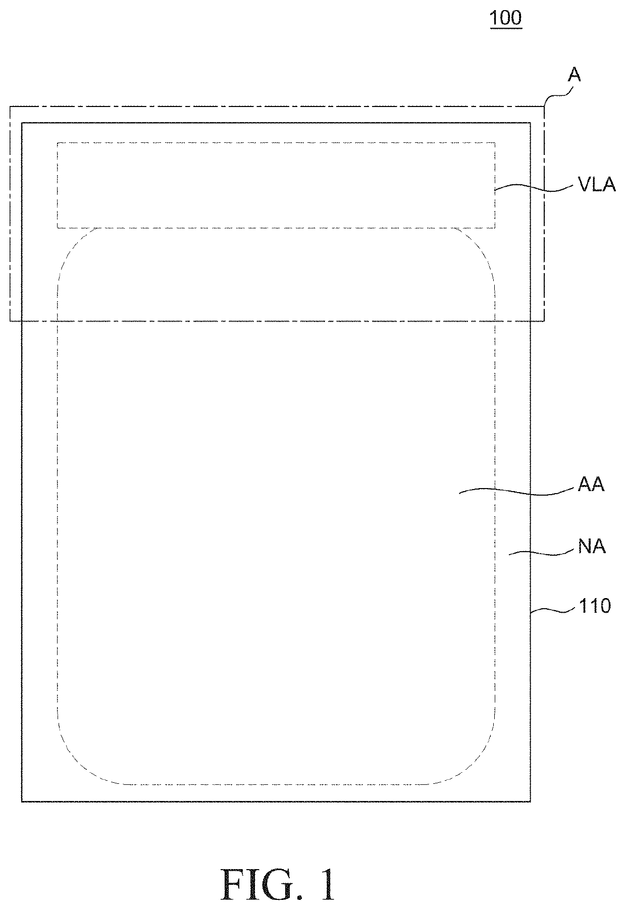
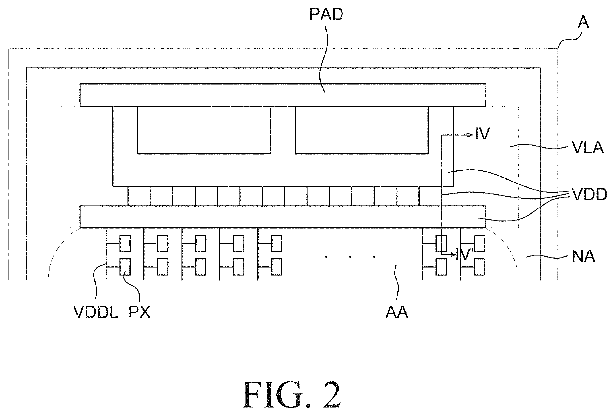
This patent describes a new display apparatus that can reduce voltage drops and improve brightness uniformity. The technical effect of the patent is to minimize the voltage drop caused by a high-potential voltage by disposing an additional wiring connected to the power wirings in an empty area of the touch part. This results in a more uniform supply of power to all pixels, resulting in improved brightness uniformity. Additionally, the display apparatus can have a reduced space for power wirings in the display area, which can result in a limitation that a width of each power wiring has decreased.

Problems solved by technology

However, in accordance with the high resolution of the display apparatus, the display apparatus can have a reduced space for the power wirings in the display area, which can result in a limitation that a width of each power wiring has decreased.
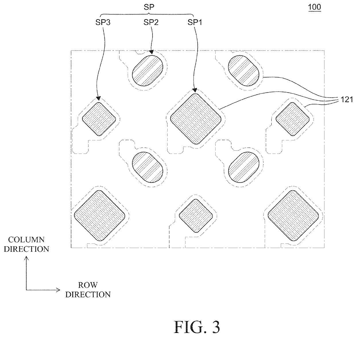
However, in the pentile-structure pixel arrangement, when designing an additional wiring in the display area, the additional wiring needs to avoid pre-existing power wirings and anodes, which can result in a limitation that the length of the additional wiring may increase, thereby causing an increase in resistance of the additional wiring.
Further, there has been another limitation that no process margin may remain between the additional wiring and the power wirings and anodes, and as a result, there may be a region in which another additional wiring cannot be designed.

Method used


Image

  • Light emitting display apparatus
  • Light emitting display apparatus
  • Light emitting display apparatus

Examples


Embodiment Construction

[0027]Reference will now be made in detail to embodiments of the present disclosure, examples of which may be illustrated in the accompanying drawings. In the following description, when a detailed description of well-known functions or configurations related to this document is determined to unnecessarily cloud a gist of the inventive concept, the detailed description thereof will be omitted. The progression of processing steps and / or operations described is an example; however, the sequence of steps and / or operations is not limited to that set forth herein and can be changed as is known in the art, with the exception of steps and / or operations necessarily occurring in a particular order. Like reference numerals designate like elements throughout. Names of the respective elements used in the following explanations are selected only for convenience of writing the specification and can be thus different from those used in actual products.

[0028]Advantages and features of the present d...


PUM


Abstract

A light emitting display apparatus can include a substrate including a display area, and a non-display area outside of the display area; a power supply wiring part disposed in the non-display area; a first power supply wiring disposed in the power supply wiring part; a second power supply wiring disposed on the first power supply wiring; and a third power supply wiring electrically connected to the second power supply wiring.

Description

CROSS-REFERENCE TO RELATED APPLICATIONS[0001]This application claims the priority benefit of Korean Patent Application No. 10-2020-0127074 filed on Sep. 29, 2020, in the Republic of Korea, the entirety of which is incorporated herein by reference into the present application.BACKGROUNDTechnical Field[0002]The present disclosure relates to a light emitting display apparatus, and more particularly, to a light emitting display apparatus having improved brightness uniformity.Description of the Related Art[0003]Unlike a liquid crystal display apparatus, a light emitting display apparatus does not require a separate light source (e.g., a backlight is not needed), and thus can be manufactured in a lightweight and thin form. In addition, the light emitting display apparatus is not only advantageous in terms of power consumption because it is driven at a low voltage, but also excellent in color implementation, response speed, viewing angle, and contrast ratio CR. Accordingly, the light emitt...

Claims


Application Information

Patent Timeline
IPC IPC(8): G06F3/041G06F1/18
CPCG06F3/04164G06F3/0412G06F1/189G06F1/1626G06F3/0445H01L27/124H10K59/353H10K59/40H10K59/1213H10K59/131H10K50/81
Inventor JUN, HYOYOUNG
Owner LG DISPLAY CO LTD
Learn More