Optical-electrical module

Inactive Publication Date: 2013-06-20
HON HAI PRECISION IND CO LTD
View PDF1 Cites 4 Cited by
  • Summary
  • Abstract
  • Description
  • Claims
  • Application Information

AI Technical Summary

Benefits of technology

The present patent relates to optical-electrical modules for data transmission. The technical problem addressed in the patent is the attenuation of optical signals caused by the fixed perpendicular of the optical signals to the base board where the transmitted optical signals need to be reflected. The patent proposes an optical-electrical module that overcomes this problem by providing a reflector that can be adjusted to parallel the optical signals to the base board, reducing attenuation.

Problems solved by technology

This causes attenuation of the optical signals.

Method used


Image

  • Optical-electrical module
  • Optical-electrical module
  • Optical-electrical module

Examples


Embodiment Construction

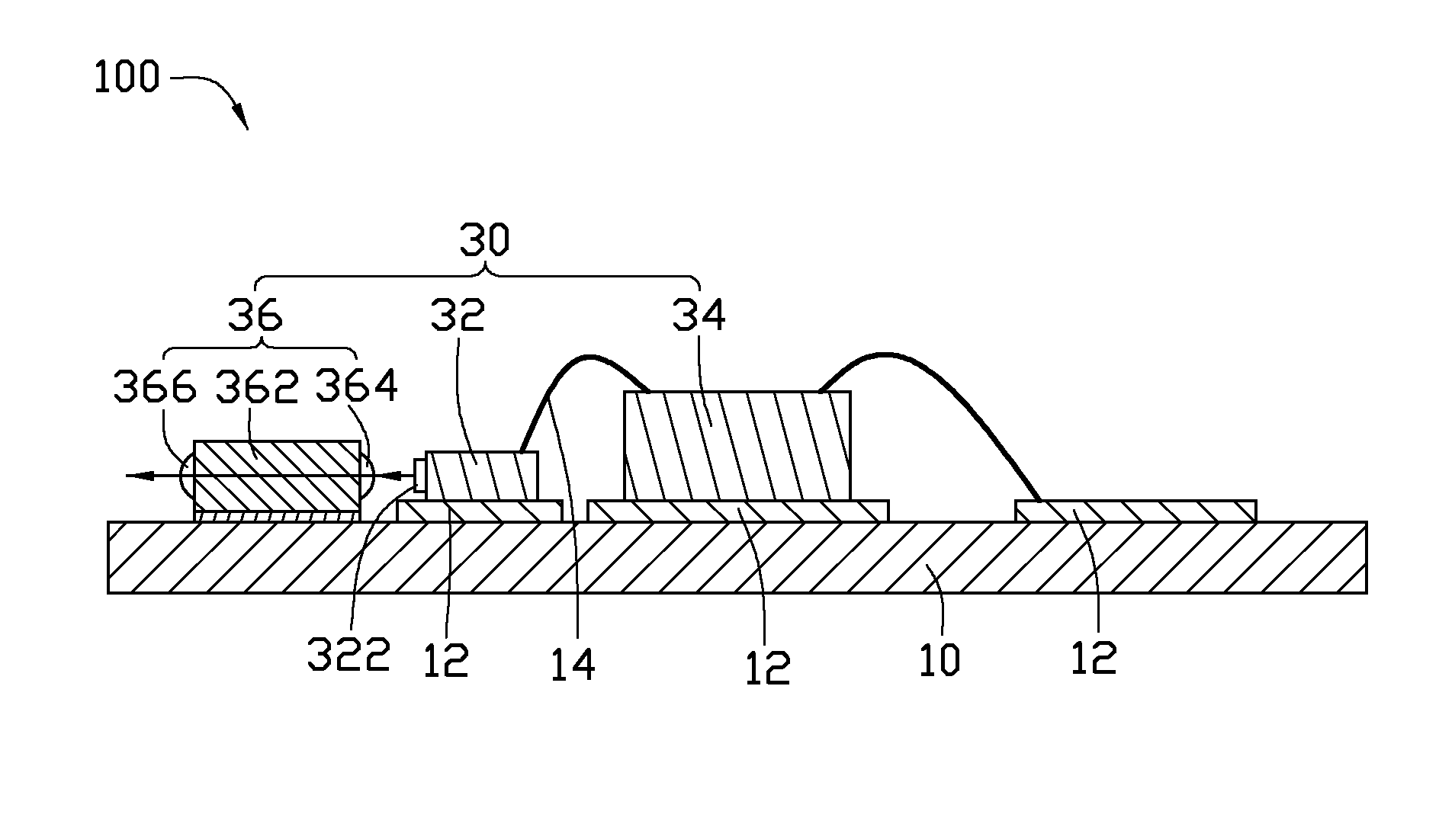
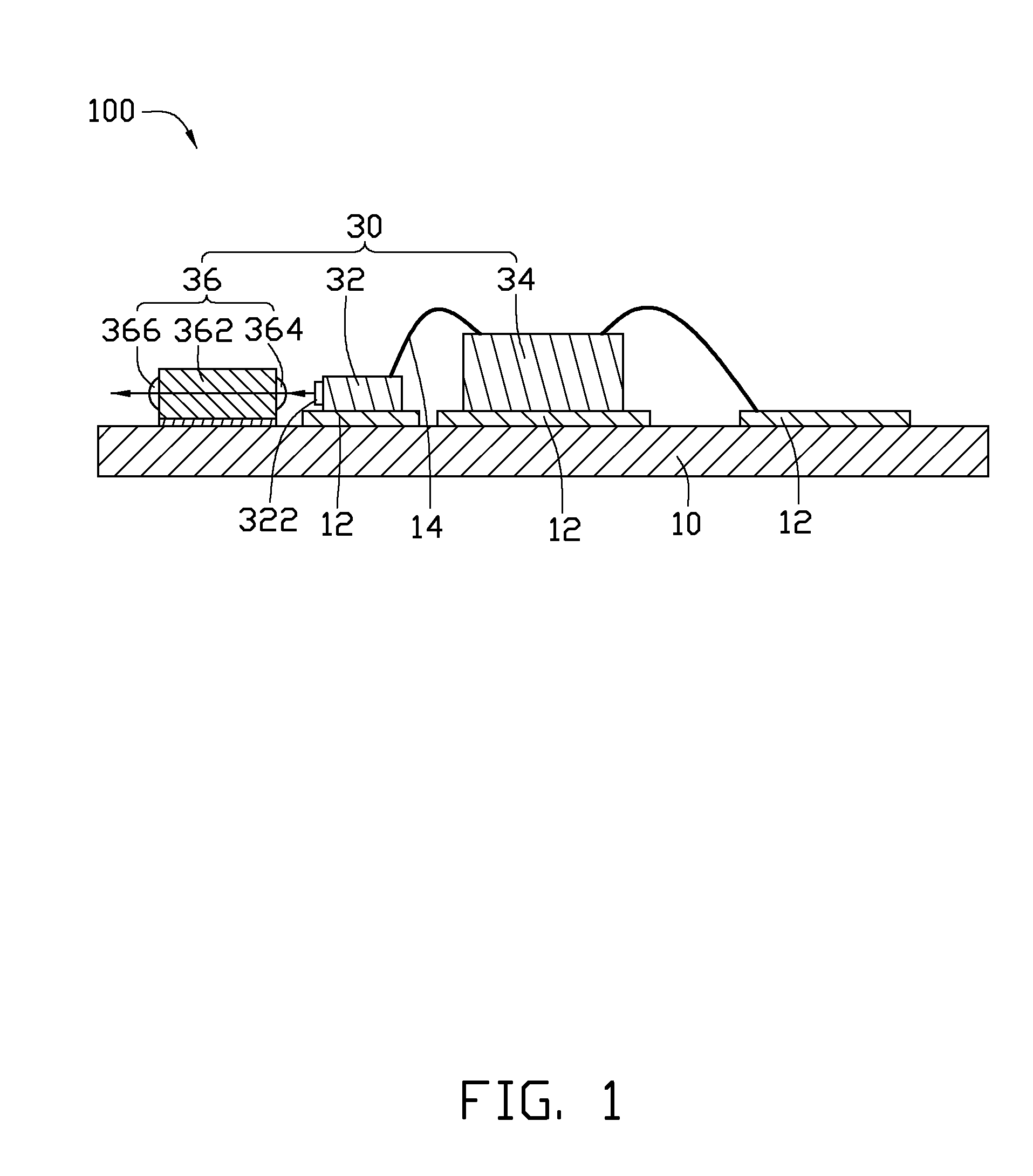
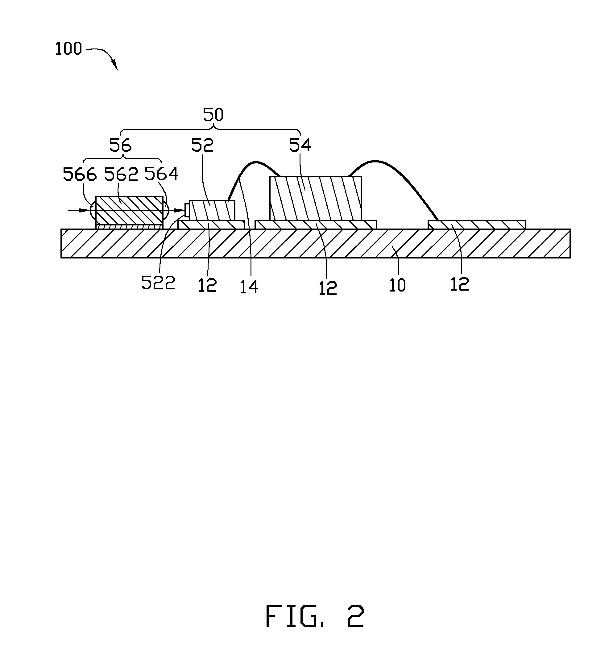
[0009]Referring to FIGS. 1 and 2, an embodiment of an optical-electrical module 100 for data transmission is shown. The optical-electrical module 100 comprises a base board 10, an optical transmitting unit 30 (as shown in FIG. 1) and an optical receiving unit 50 (as shown in FIG. 2) fixed on the base board 10 adjacent to the optical transmitting unit 30.

[0010]The base board 10 is an integrated circuit board. A plurality of solder masks 12 are formed on the surface of the base board 10. The optical transmitting unit 30 comprises an edge-emitting laser 32, a driving integrated circuit 34, and a first lens unit 36. The edge-emitting laser 32 and the driving integrated circuit 34 configured next to each other are both fixed on one solder mask 12, respectively. The edge-emitting laser 32 is electrically connected to the driving integrated circuit 34 with a wire 14.

[0011]The first lens unit 36 is fixed on the base board 10 adjacent to the edge-emitting laser 32. The first lens unit 36 com...


PUM


Abstract

An optical-electrical module includes a base board and an optical transmitting unit fixed on the base board. The optical transmitting unit includes an edge-emitting laser transmitting optical signals parallel to the base board, a driving integrated circuit for driving the edge-emitting laser to transmit optical signals, and a first lens unit for transmitting and converging the optical signals. Furthermore, the optical-electrical module can also include an optical receiving unit used to receive the optical signals transmitted by the optical transmitting unit and convert the optical signals into electrical signals. The optical receiving unit includes a photo diode, a transimpedance amplifier, and a second lens unit.

Description

BACKGROUND[0001]1. Technical Field[0002]The present disclosure relates to optical-electrical modules, particularly to an optical-electrical module configured for data transmission.[0003]2. Description of Related Art[0004]Many optical-electrical modules for data transmission include a vertical-cavity-surface-emitting laser (VCSEL), a driving integrated circuit used for driving the vertical-cavity surface-emitting laser to transmit optical signals, and a lens unit for converging the optical signals or changing the transmission direction of the optical signals. However, the optical-electrical module is fixed perpendicular to a base board where the transmitted optical signals of the VCSEL need to be reflected to be parallel to the base board by a reflector. This causes attenuation of the optical signals.[0005]Therefore, there is room for improvement in the art.BRIEF DESCRIPTION OF THE DRAWINGS[0006]Many aspects of the disclosure can be better understood with reference to the following d...

Claims


Application Information

Patent Timeline
IPC IPC(8): G02B6/32
CPCG02B6/4201
Inventor WU, KAI-WEN
Owner HON HAI PRECISION IND CO LTD
Why Eureka
Try Eureka