Installation or device with a high-definition multimedia interface

a multimedia interface and installation device technology, applied in the direction of instruments, television systems, power supply for data processing, etc., can solve the problems of increasing the cumulative standby power consumption of hdmi equipped audio/video devices, and the potential for large energy saving potential

Inactive Publication Date: 2013-06-20
EM MICROELECTRONIC-MARIN +1
View PDF6 Cites 10 Cited by
  • Summary
  • Abstract
  • Description
  • Claims
  • Application Information

AI Technical Summary

Benefits of technology

[0010]Cumulative stand-by power consumption of HDMI equipped audio / video devices is increasing and will be very large in a near future. Thus, there is a large energy savings potential by reducing this electrical consumption to the lowest level. Since operating an HDMI involves at least two and in many cases several devices and systems, the standby energy consumption is multiplied accordingly.

Problems solved by technology

Cumulative stand-by power consumption of HDMI equipped audio / video devices is increasing and will be very large in a near future.

Method used


Image

  • Installation or device with a high-definition multimedia interface
  • Installation or device with a high-definition multimedia interface
  • Installation or device with a high-definition multimedia interface

Examples


first embodiment

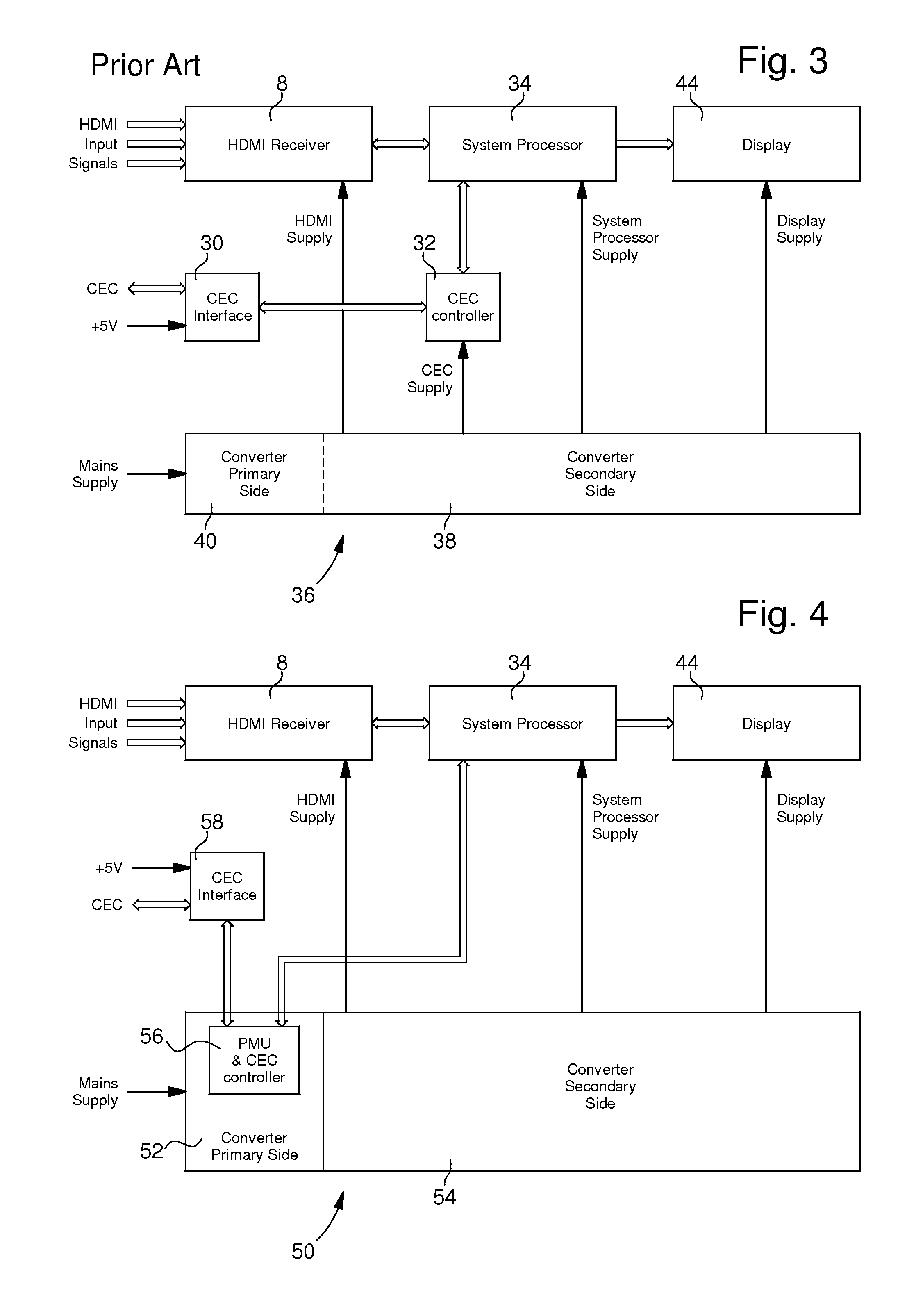
[0024]The architecture diagram of an installation or device according to the present invention is shown in FIG. 4. More particularly, this FIG. 4 represents a HDMI digital TV. The supply of the display 44 can be made by a specific converter and associated circuits.

[0025]According to this first embodiment, the CEC controller is arranged on the converter primary side 52 of the power supply unit 50 and controls all CEC communication between the corresponding HDMI device and other HDMI devices of the system. In a preferred variant, the electrical supply of this CEC controller is provided, at least in Standby or Power-down mode, through the secondary power supply of the Power Management Unit (PMU) arranged on the primary side of the converter, as described in document WO 2010 / 003785 which is enclosed by reference in the present description. Thus, this variant has no CEC controller on the secondary side of the power unit but a CEC controller incorporated in a “PMU & CEC controller” electr...

second embodiment

[0035]It is to be noted that a same CEC interface can be implemented in the CEC Interface 68 of an installation or device previously described for the communication toward the “PMU & CEC receiver” electronic part 62 (FIG. 5). Such a CEC interface can be arranged in parallel with a standard interface with the CEC controller 66. Other variants for the CEC interface 68 can be provided by a person skilled in the art wherein both interfaces to the CEC receiver and controller are combined.

[0036]A specific application of the present invention, based on the second embodiment of an installation or device previously described, is outlined on the example of wake-up and standby operations of a HDMI-equipped DVD player. Waking up such a DVD player is achieved through the HDMI-defined CEC protocol. In the low power mode (Standby or Power-down mode) only the “PMU & CEC Receiver” electronic part is supplied while the rest of the system is not powered. The corresponding MCU receives commands over th...


PUM


Abstract

The Installation is equipped with a power supply unit and a High-Definition Multimedia Interface (HDMI), this installation being able to be connected to a second HDMI device with which it can communicate by using a protocol defined in the HDMI Standard, this installation or device being able to be set in Standby or Power-down mode and to be removed from this Standby or Power-down mode by said second HDMI device via a Consumer Electronic Control (CEC) line. The installation has a Power Management Unit (PMU) arranged on the primary side of said power supply unit, this PMU having its own power supply circuit directly connected to the power supply source of this installation or device and being arranged for switching OFF the electrical energy on the secondary side of said power supply unit when this installation or device enters said Standby or Power-down mode.

Description

FIELD OF THE INVENTION[0001]The invention concerns an electrical installation or device having a power supply equipped with a voltage converter or transformer and a High-Definition Multimedia Interface (HDMI).[0002]In particular, the invention may be implemented in audio / video consumer electronic devices equipped with HDMI functionality, such as a digital TV set, a display or a computer screen, a DVD player, a decoder or a demodulator (Set-Top Box), in entertainment devices like electronic play stations, etc.BACKGROUND OF THE INVENTION[0003]Systems with high speed, high quality audio / video interfaces have been offered in the market since shortly after the release of the HDMI standards around 2002.[0004]The general structure of such an HDMI is shown in FIG. 1. Video and audio information is transmitted between a “source” part 2 of a first device having a HDMI transmitter 4 (e.g. DVD player, a set top box) and a “sink” part 6 of a second device having a HDMI Receiver 8 (e.g. a display...

Claims


Application Information

Patent Timeline
Patent Type & Authority Applications(United States)
IPC IPC(8): G06F1/32
CPCH04N5/4403H04N5/63H04N5/765H04N21/4436H04N21/43615H04N21/43635G06F1/3253H04N21/42204
Inventor THEODULOZ, YVESFISCH, JOSEFSCHLENK, MANFREDMAUPAS, FABIEN
Owner EM MICROELECTRONIC-MARIN
Why Eureka
Try Eureka