Evaporation cell and vacuum deposition system the same

Inactive Publication Date: 2013-06-27
SHARP KK
View PDF7 Cites 6 Cited by
  • Summary
  • Abstract
  • Description
  • Claims
  • Application Information

AI Technical Summary

Benefits of technology

[0021]According to the present disclosure, the preliminary heating means preliminarily heats the organic deposition material, and the preliminarily heated material is then primarily heated by the primary heating means. Accordingly, when the organic deposition material is subjected to vapor deposition, it is poss

Problems solved by technology

In such a case, the organic deposition material has low thermal responsiveness, and accordingly, it is difficult to increase the temperature of the organic deposition material by indirectly heating the organic deposition material through the cruci

Method used


Image

  • Evaporation cell and vacuum deposition system the same
  • Evaporation cell and vacuum deposition system the same
  • Evaporation cell and vacuum deposition system the same

Examples


Example

[0027]An embodiment of the present disclosure will be described below with reference to the drawings. Note that the present disclosure is not limited to the embodiment described below.

Embodiment of Disclosure

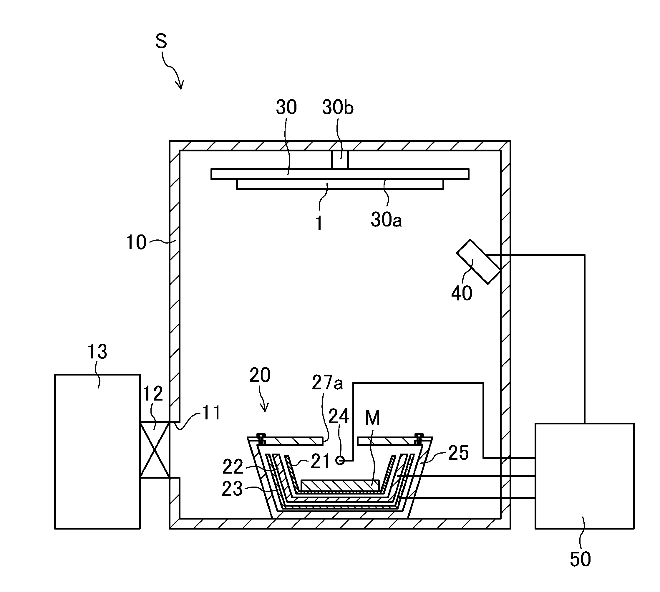
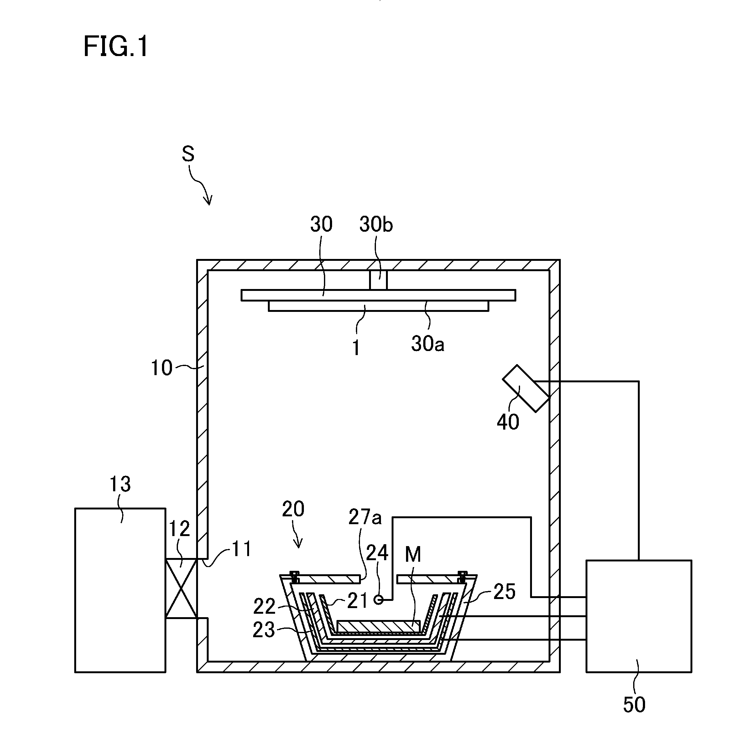
[0028]FIG. 1 schematically illustrates a configuration of a vacuum deposition system S according to this embodiment.

[0029]The vacuum deposition system S is used to form an organic film by depositing an organic material on a surface of a target substrate 1 such as a glass substrate. The vacuum deposition system S includes a vacuum chamber 10, an evaporation cell 20 provided near the bottom of the vacuum chamber 10, a substrate holder 30 provided near the ceiling of the vacuum chamber 10 so as to hold the target substrate 1 at a position above and opposite to the evaporation cell 20, a deposition rate sensor 40 provided at a position located at a side of the substrate holder 30 and nearer a substrate holding face 30a of the substrate holder 30, and a controller 50.

[0030]The vacuu...


PUM

PropertyMeasurementUnit
Temperatureaaaaaaaaaa
Boiling pointaaaaaaaaaa
Temperatureaaaaaaaaaa

Abstract

An evaporation cell includes a crucible (21) containing a deposition material (M), an electric heater (22) which heats the crucible (21) and thereby preliminarily heats the deposition material (M) contained in the crucible (21) in an indirect manner to a temperature range in which vaporization of the deposition material (M) does not occur; and a lamp heater (24) which directly heats the deposition material (M) contained in the crucible (21) and thereby primarily heats the preliminarily heated deposition material (M) to a temperature equal to or higher than its vaporization temperature.

Description

TECHNICAL FIELD[0001]The present disclosure relates to evaporation cells and vacuum deposition systems including the same, and particularly to measures against deterioration of organic materials which is caused when the organic materials are subjected to vapor deposition.BACKGROUND ART[0002]Vapor deposition performed in a vacuum deposition system is widely used to, for example, form an organic electro luminescence (EL) layer in processes of producing organic EL devices. Resistance heating type deposition systems are vacuum deposition systems which are generally used, and each include a vacuum chamber having an evaporation cell provided therein and a substrate holder for holding a target substrate at a position above and opposite to the evaporation cell. The evaporation cell includes a ceramic crucible for containing, e.g., a conductive deposition material, and a heater for heating the crucible. The evaporation cell indirectly heats the deposition material contained in the crucible b...

Claims


Application Information

Patent Timeline
IPC IPC(8): C23C16/448
CPCC23C14/12C23C14/243C23C16/4485H01L51/001H05B33/10C23C14/26H10K71/164
Inventor NIBOSHI, MANABU
Owner SHARP KK
Why Eureka
Try Eureka