Electronic throttle on control handle

a control handle and electronic technology, applied in electrical control, mechanical control devices, instruments, etc., can solve the problems of poor quality and/or low production, fatigue of operators, and difficult operation of work vehicles and work implements, and achieve the effect of reliable achievemen

Inactive Publication Date: 2013-06-27
CNH IND AMERICA LLC
View PDF30 Cites 8 Cited by
  • Summary
  • Abstract
  • Description
  • Claims
  • Application Information

AI Technical Summary

Benefits of technology

[0011]The invention is also directed to a device for control of a vehicle which is arranged in an operator compartment in proximity to the operator. The device includes a multi-function control handle which has a gripping portion with a plurality of control elements. The control elements are constructed and arranged so that they can reliably be reached with one or two digits of a hand of the operator resting on the gripping portion. The device further includes an actuating element for changing the speed of the engine of the vehicle. The actuating element is conveniently movable by an operator's digit to a plurality of positions to effect the desired engine speed.

Problems solved by technology

These work vehicles and work implements can be relatively complicated and difficult to operate.
After a period of operating these control mechanisms, the operators may become fatigued.
In addition, because the operator's hand may be required to travel from one actuating element to another, an operator's delayed reaction time, as well as the complexity and counter-intuitiveness of the controls, may result in poor quality and / or low production.
The operator must take his / her hand off the vehicle control lever in order to adjust the throttle, thereby creating safety and worker fatigue issues during operation of the vehicle.

Method used


Image

  • Electronic throttle on control handle
  • Electronic throttle on control handle
  • Electronic throttle on control handle

Examples


Embodiment Construction

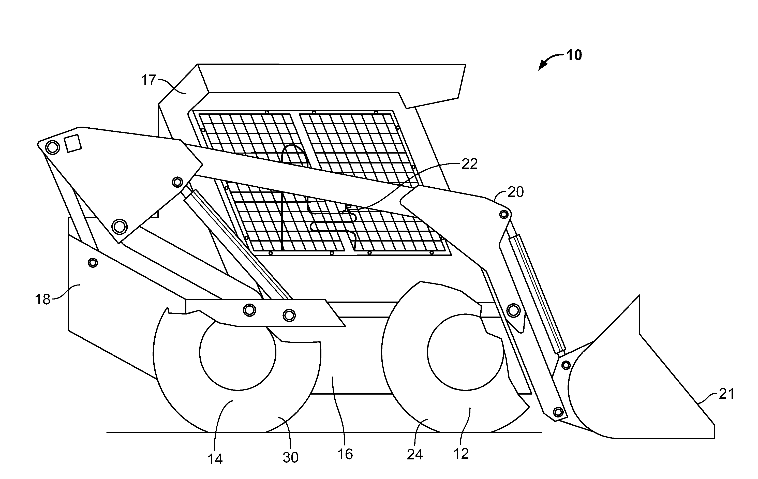
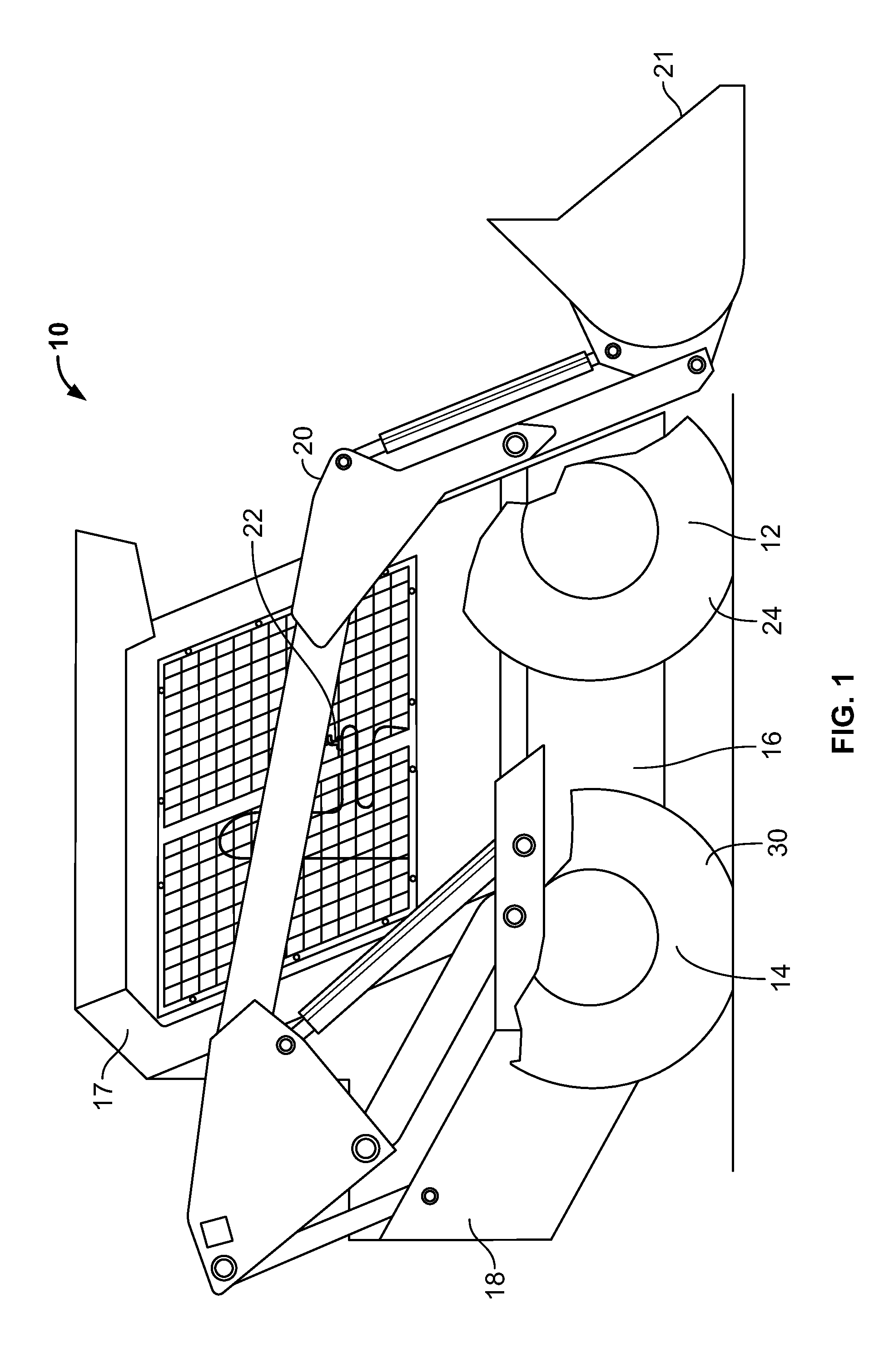
[0018]An exemplary embodiment of a work vehicle 10 is illustrated in FIG. 1. Although a skid-steer loader is shown, the work vehicle 10 may be a motor grader, a backhoe loader, an agricultural tractor, a wheel loader, or any other type of work vehicle known in the art. Work vehicle 10 may include a steerable traction device 12, a driven traction device 14, a frame 16 connecting steerable traction device 12 to driven traction device 14, an operator compartment 17 on the frame 16, a power source 18 supported by the driven traction device 14, and a transmission (not shown) configured to transmit power from the power source 18 to the driven traction device 14. The work vehicle 10 may also include a work implement such as, for example, a lift assembly 20 with a bucket 21 attached thereto, and a control mechanism 22.

[0019]The steerable traction device 12 may include one or more wheels 24 located on each side of the work vehicle 10 (only one side shown). Alternatively, the steerable tracti...


PUM


Abstract

A steering and engine speed control mechanism for operating a vehicle. The control mechanism has a control handle mounted on the vehicle. The control handle is configured to deflect about an axis by movement of an operator's hand. A steering direction of the vehicle is related to a deflection angle of the control handle about the axis. An actuating element for changing the speed of the engine of the vehicle is attached to the control handle and is conveniently movable by an operator's digit to a plurality of positions to effect the desired speed of the engine.

Description

CROSS REFERENCE TO RELATED APPLICATIONS[0001]This application is a divisional of U.S. patent application Ser. No. 12 / 581,616, entitled “ELECTRONIC THROTTLE ON CONTROL HANDLE,” filed Oct. 19,2009, which is hereby incorporated by reference in its entirety.FIELD OF THE INVENTION[0002]The present disclosure is directed to a control mechanism for a work vehicle and, more particularly, to a control handle mechanism for a work vehicle.BACKGROUND OF THE INVENTION[0003]Work vehicles such as, for example, motor graders, backhoe loaders, agricultural tractors, wheel loaders, skid-steer loaders, and other types of heavy vehicles are used for a variety of tasks requiring operator control of the work vehicle and various work implements associated with the work vehicle. These work vehicles and work implements can be relatively complicated and difficult to operate. They may have an operator interface with numerous controls for steering, position, orientation, transmission gear ratio, and travel spe...

Claims


Application Information

Patent Timeline
Patent Type & Authority Applications(United States)
IPC IPC(8): F02D41/00
CPCG05G9/04788F02D11/10E02F9/2066B60K2026/029E02F9/2004G05G9/00
Inventor CASE, MICHAEL D.BIGGERSTAFF, JOSEPH M.HAAR, WILLIAM RYANNEWLIN, TIMPOTTER, ERIC
Owner CNH IND AMERICA LLC
Why Eureka
Try Eureka