Switching apparatus
- Summary
- Abstract
- Description
- Claims
- Application Information
AI Technical Summary
Benefits of technology
Problems solved by technology
Method used
Image
Examples
embodiment 1
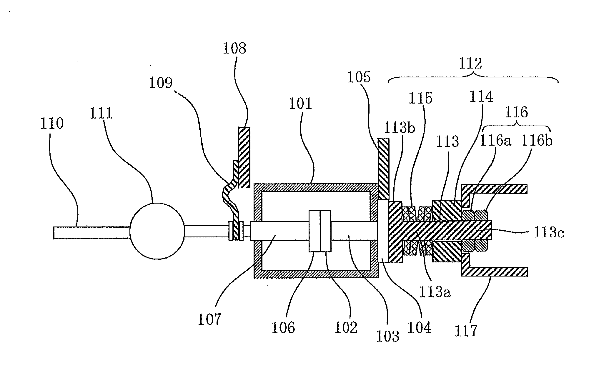
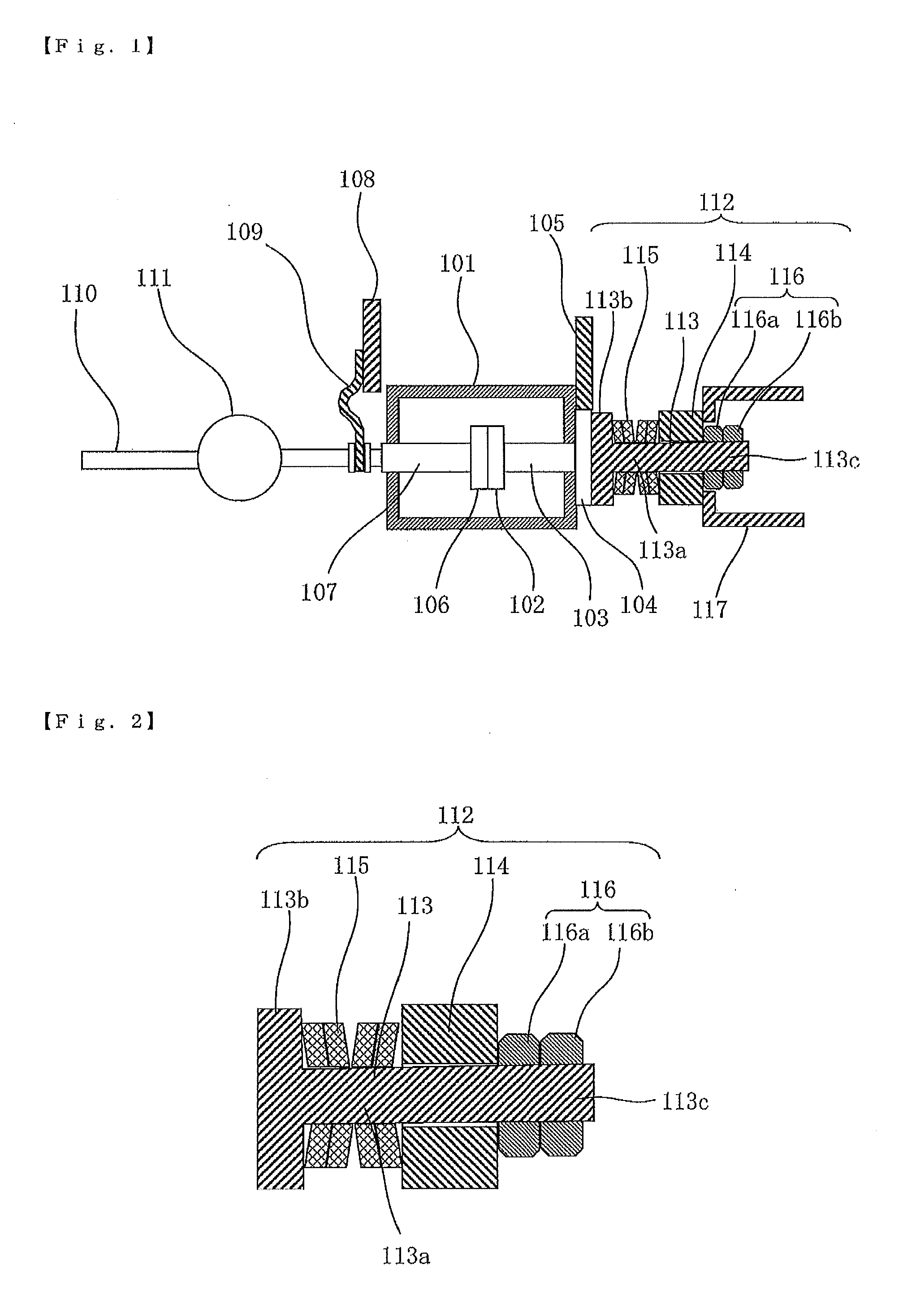
[0022]Hereinafter, Embodiment 1 of the present invention will be described with reference to FIG. 1 to FIG. 2. Then, in each of the drawings, identical or equivalent members and portions will be described with the same reference numerals assigned thereto. FIG. 1 is a sectional view showing a switching apparatus according to Embodiment 1 of the present invention. FIG. 2 is a sectional view showing a buffering mechanism in the switching apparatus according to Embodiment 1 of the present invention.
[0023]Reference numeral 101 denotes a vacuum valve; and 102 denotes a fixed side electrode which is arranged in the vacuum valve 101 and is fixed to a fixed current-carrying shaft 103. The fixed side electrode 102 is electrically connected to a fixed conductor 104 and a fixed side terminal conductor 105 via the fixed current-carrying shaft 103. 106 denotes a movable side electrode which is arranged in the vacuum valve 101 and is fixed to a movable current-carrying shaft 107 coaxially arranged...
embodiment 2
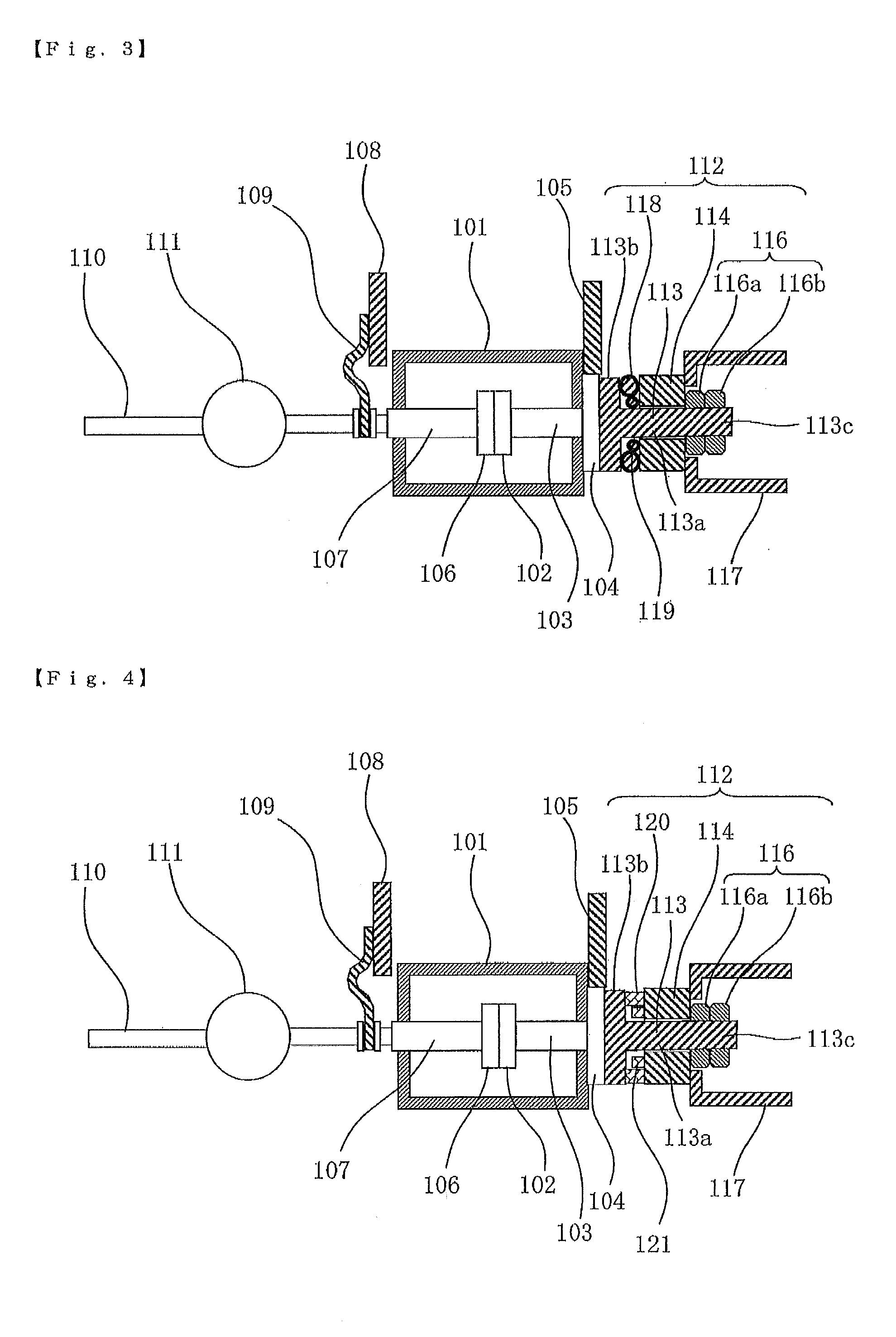
[0038]Embodiment 2 of the present invention will be described with reference to FIG. 3. Then, in the drawing, identical or equivalent members and portions will be described with the same reference numerals assigned thereto. FIG. 3 is a sectional view showing a switching apparatus according to Embodiment 2 of the present invention.
[0039]The description has been made on the case where the elastic body 115 is formed by the coned disc springs in the aforementioned Embodiment 1; however, in Embodiment 2, an elastic body 118 is formed of a rubber material. The drawing shows the elastic body 118 formed by an O-ring as an example.
[0040]According to Embodiment 2, load adjustment is performed in a compressed state of the O-ring serving as the elastic body 118; and similar effects to the aforementioned Embodiment 1 can be exhibited.
[0041]Furthermore, a compressed state maintaining member 119, which maintains a compressed state of the O-ring at a predetermined state, is disposed on the inner ci...
embodiment 3
[0042]Embodiment 3 of the present invention will be described with reference to FIG. 4 to FIG. 5. Then, in each of the drawings, identical or equivalent members and portions will be described with the same reference numerals assigned thereto. FIG. 4 is a sectional view showing a switching apparatus according to Embodiment 3 of the present invention. FIG. 5 is a relevant part sectional side view of FIG. 4 showing the switching apparatus according to Embodiment 3 of the present invention.
[0043]The description has been made on the case where the elastic body 118 is formed by the O-ring made of the rubber material in the aforementioned Embodiment 2; and in the case where the load adjustment of the elastic body 118 cannot be performed within a compression range of the O-ring, the elastic body 118 formed by the O-ring needs to be replaced after removing the shaft section 113a of the basic shaft 113 of the buffering mechanism 112 from the shaft support body 114. However, in Embodiment 3, a...
PUM
 Abstract
Description
Claims
Application Information
 - R&D Engineer
- R&D Manager
- IP Professional
- Industry Leading Data Capabilities
- Powerful AI technology
- Patent DNA Extraction
Browse by: Latest US Patents, China's latest patents, Technical Efficacy Thesaurus, Application Domain, Technology Topic, Popular Technical Reports.
© 2024 PatSnap. All rights reserved.Legal|Privacy policy|Modern Slavery Act Transparency Statement|Sitemap|About US| Contact US: help@patsnap.com


