Vehicle door handle device

a technology for door handles and vehicles, which is applied in the direction of doors, wing knobs, lock applications, etc., can solve the problems of reducing anti-theft reliability, affecting the operation, and unable to ensure the joint strength of the panel member, so as to achieve the effect of convenient assembly

Inactive Publication Date: 2013-06-27
AISIN SEIKI KK
View PDF8 Cites 16 Cited by
  • Summary
  • Abstract
  • Description
  • Claims
  • Application Information

AI Technical Summary

Benefits of technology

The present invention provides a vehicle door handle device that is easy to assemble and allows for smooth opening and closing of the vehicle door without creating an unnatural sensation. The device is designed so that the hand grip is supported in a freely pivotable manner by the holder member and the frame member, allowing for easy assembly. The hand grip is guided by a guide projection fitted in a guide groove, which ensures stable movement. The arcuate surface of the operational portion slides on the transmitting member, reducing the force required for operation. Overall, the device improves operational reliability and reduces the force required for operation.

Problems solved by technology

In this case, however, the entire component is virtually exposed to the outside of the vehicle, which lowers the antitheft reliability.
Also, sufficient joint strength with the panel member may not be ensured.
This inevitably degrades the operability.

Method used


Image

  • Vehicle door handle device
  • Vehicle door handle device
  • Vehicle door handle device

Examples


first embodiment

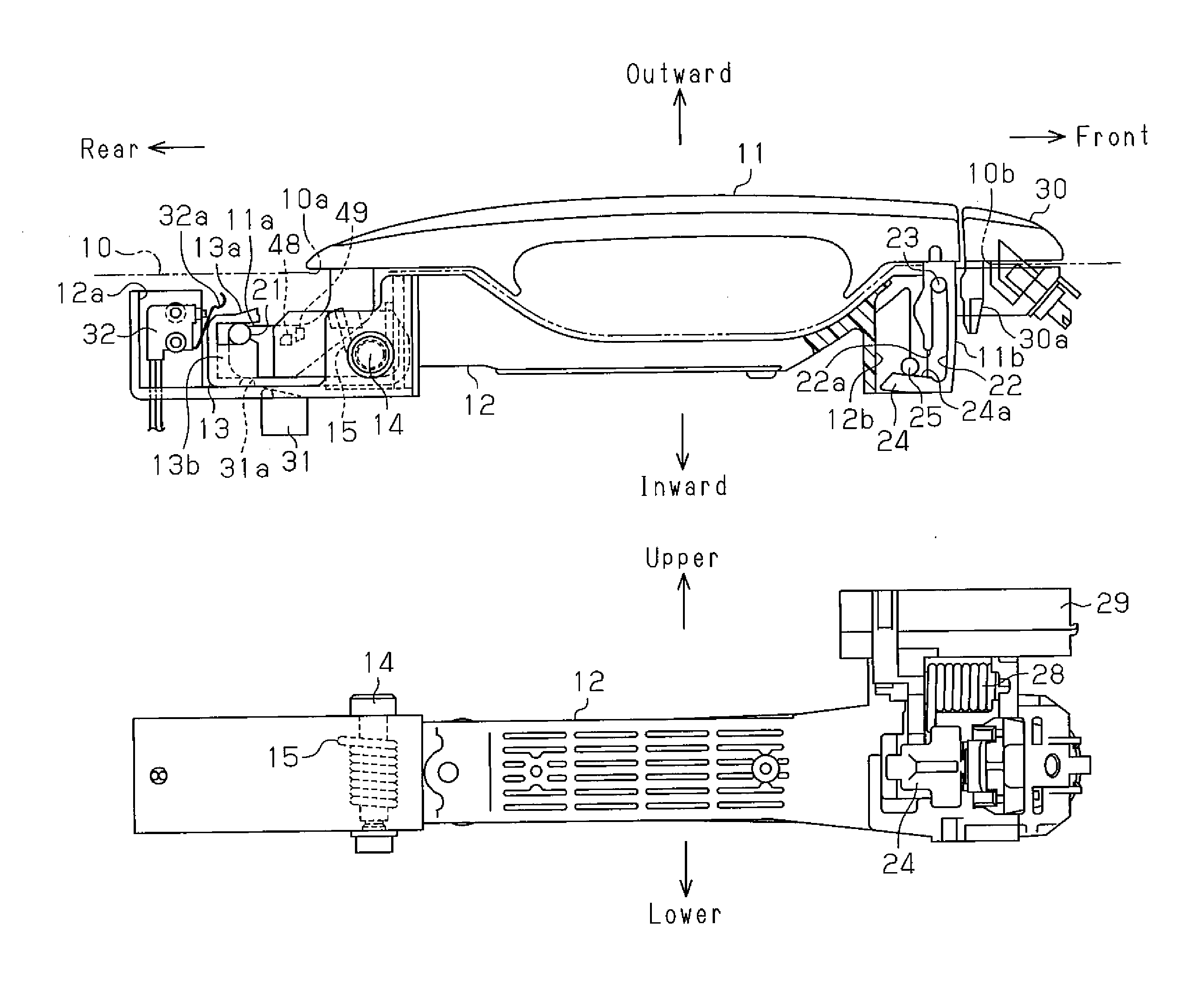
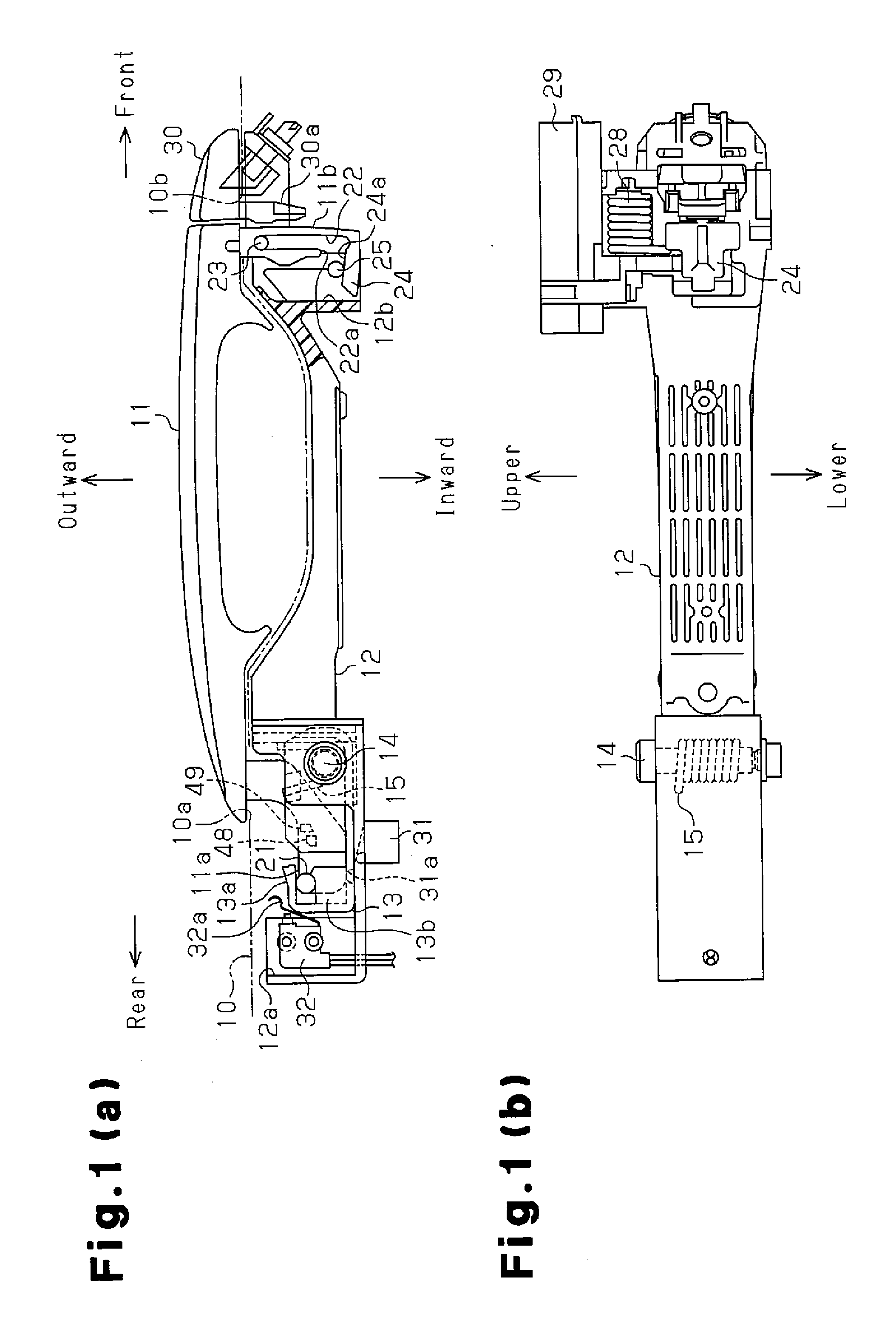
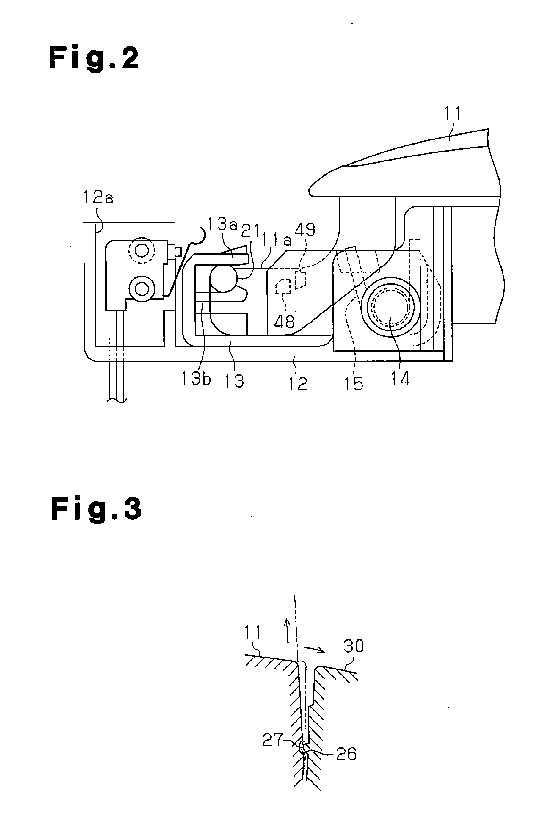
[0036]A vehicle door handle device according to a first embodiment of the present invention will now be described with reference to FIGS. 1 to 6. When describing the vehicle door handle device of the present invention, a side located closer to the vehicle outside with respect to the widthwise direction of the vehicle is referred to as an outside, and side facing the passenger compartment is referred to as an inside. Also, the advancing direction of the vehicle is referred to as the front.

[0037]As shown in FIG. 6, a sliding door 1 is moved forward or rearward to open or close an opening for allowing entry and exit formed in the vehicle body. A rear lock 2 is provided in a rear portion of the sliding door 1, and a front lock 3 is provided in a front portion of the sliding door 1. The rear lock 2 and the front lock 3 form a full close latch mechanism and hold the sliding door 1 at the fully closed state. A full open lock 4, which serves as a full open latch mechanism, is provided in a ...

second embodiment

[0071]A vehicle door handle device according to a second embodiment of the present invention will now be described with reference to FIGS. 7(a) to 7(c). The second embodiment is different from the first embodiment in the structure for supporting a holder member to a frame member. Therefore, like or the same reference numerals are given to those components that are like or the same as the corresponding components of the first embodiment.

[0072]As shown in FIG. 7(a), an elongated hole 42 is formed in the rear end of frame member 41. The elongated hole 42 extends in the up-down direction and has a pair of open ends. The cross-sectional shape of the elongated hole 42 extends in the front-rear direction. A holder member 43 is attached to the frame member 41. The holder member 43 is made of resin and formed into a substantially rectangular box. A pin 14 is loosely fitted in the elongated hole 42. The holder member 43 is coupled to the frame member 41 to be pivotable about the pin 14. The h...


PUM


Abstract

A hand grip has an arm and a leg. The arm and the leg extend through a door outer panel and are supported by a holder member and a frame member in a freely pivotable manner, respectively. By operating the hand grip in the same direction as when a sliding door is opened, the arm is pivoted relative to the holder member retained at an initial position, so that a full close latch mechanism is unlocked. By operating the hand grip in the same direction as when the sliding door is closed, the leg is pivoted relative to the frame member, while the holder member is pivoted relative to the frame member against urging force of a coil spring, so that a full open latch mechanism is unlocked.

Description

FIELD OF THE INVENTION[0001]The present invention relates to a vehicle door handle device that is operated when opening and closing a vehicle sliding door from outside the vehicle.BACKGROUND OF THE INVENTION[0002]Japanese Laid-Open Patent Publication No. 2007-85032 discloses a vehicle door handle device that includes a frame member, a hand grip, and a link mechanism. The frame member is fixed to the inner side of a panel member forming a vehicle door. The hand grip is provided on the outer side of the panel member and is engaged with and supported by the frame member. The link mechanism is interposed between the frame member and the hand grip. When opening the fully closed door, the hand grip is pulled in the same direction as a first direction along which the vehicle door is moved. This unlocks a full close lock mechanism. When closing the fully opened vehicle door, the hand grip is operated in a second direction along which the vehicle door is moved, that is, in a direction opposi...

Claims


Application Information

Patent Timeline
IPC IPC(8): E05B65/12B60J5/04B60J5/06E05B1/00E05B79/06E05B83/40E05B85/16
CPCE05B85/14E05B83/40E05B2065/0805E05B85/16Y10T292/57Y10T292/85Y10T292/88Y10T292/91
Inventor ISHIDA, TOSHIHIKO
Owner AISIN SEIKI KK
Why Eureka
Try Eureka