Power supply device, power receiving device and vehicle including power receiving device, and control method for power supply system

a technology of power supply device and power receiving device, which is applied in the direction of charging stations, rail devices, transportation and packaging, etc., can solve the problem of useless consumption of electric power, and achieve the effect of preventing the impedance of the power transmitting uni

Active Publication Date: 2013-06-27
TOYOTA JIDOSHA KK
View PDF9 Cites 21 Cited by
  • Summary
  • Abstract
  • Description
  • Claims
  • Application Information

AI Technical Summary

Benefits of technology

[0029]Thus, according to the above-described aspects of the invention, it is possible to prevent the impedance of the power transmitting unit from matching the impedance o

Problems solved by technology

When the voltage applied to the primary-side resonance unit (i.e., the power transmitting unit) is changed, the impedance of the power transmitting unit may match the imped

Method used


Image

  • Power supply device, power receiving device and vehicle including power receiving device, and control method for power supply system
  • Power supply device, power receiving device and vehicle including power receiving device, and control method for power supply system
  • Power supply device, power receiving device and vehicle including power receiving device, and control method for power supply system

Examples


Embodiment Construction

[0038]Hereinafter, embodiments of the invention will be described in detail with reference to the drawings. In the drawings, the same or corresponding portions will be denoted by the same reference numerals, and the description thereof will not be repeated.

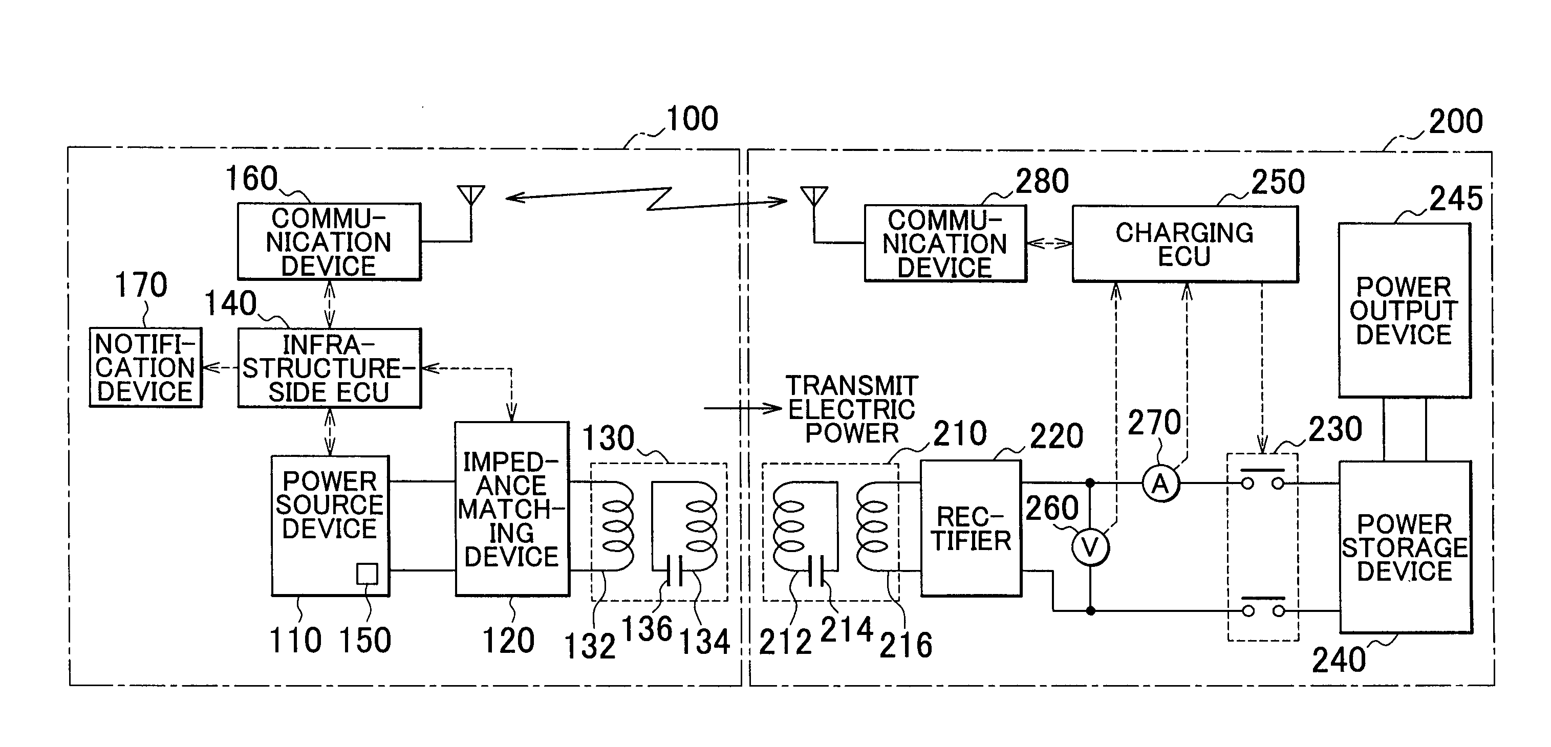
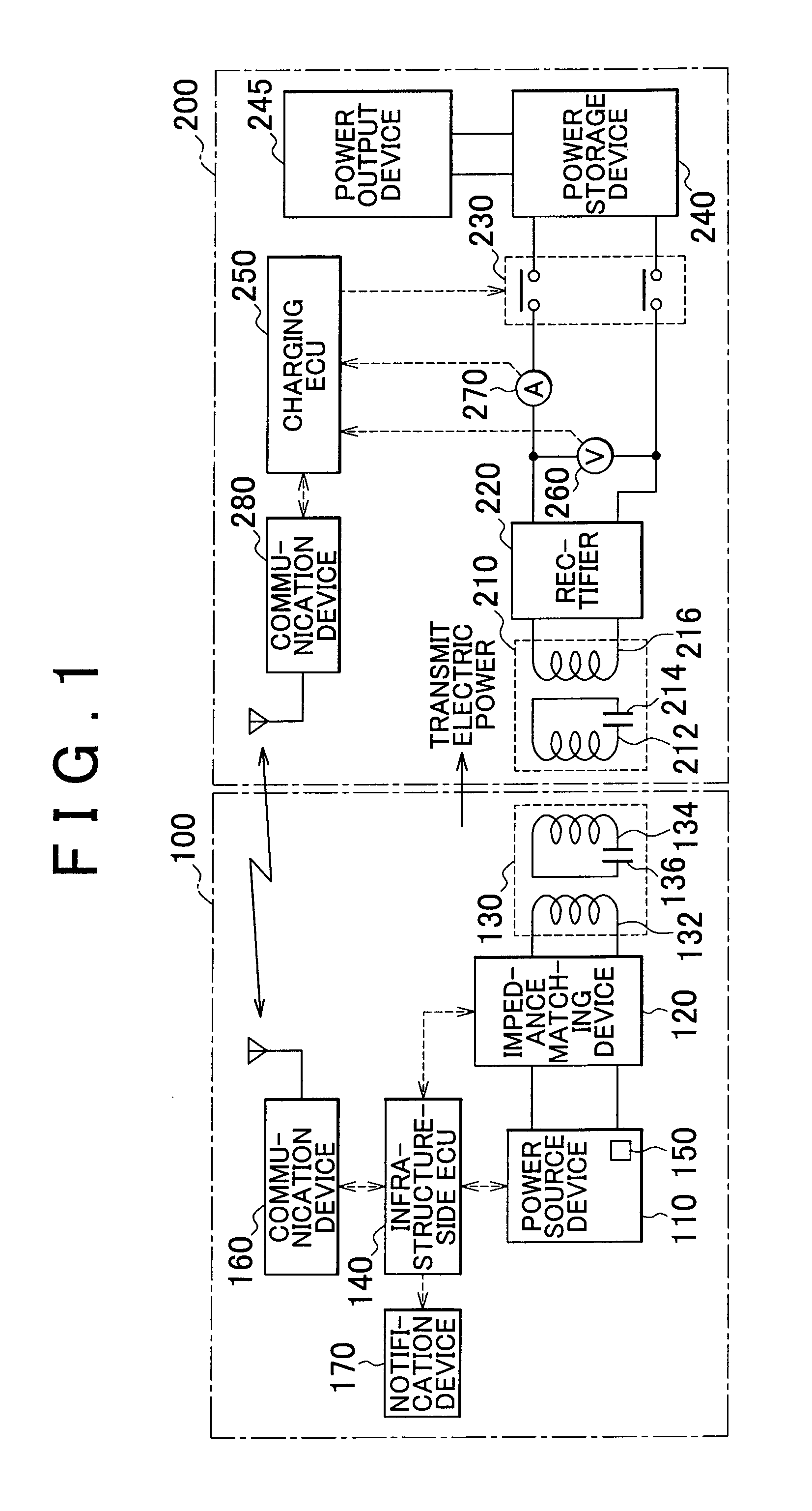
[0039]FIG. 1 is a functional block diagram showing the entire configuration of a vehicle power supply system according to an embodiment of the invention. As shown in FIG. 1, the vehicle power supply system includes a power supply device 100 and a vehicle 200.

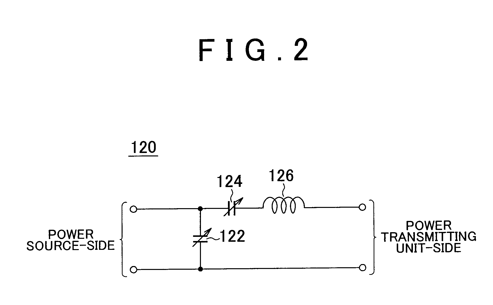
[0040]The power supply device 100 includes a power source device 110, an impedance matching device 120, a power transmitting unit 130, an infrastructure-side electronic control unit (ECU) 140 (hereinafter, simply referred to as “ECU 140”), an electric power sensor 150, a communication device 160, and a notification device 170.

[0041]The power source device 110 generates electric power having a predetermined frequency. For example, the power source device 110 receives electric p...


PUM


Abstract

A power supply device supplies electric power to a power receiving device including a power receiving unit in a non-contact manner. The power supply device includes a power source device that generates electric power with a predetermined frequency; a power transmitting unit that receives the electric power from the power source device, and that resonates with the power receiving unit through an electromagnetic field, thereby transmitting the electric power to the power receiving unit in the non-contact manner; a detection device that detects reflected electric power to the power source device; a communication device that receives information regarding a power receiving situation in the power receiving device; and a control device that controls electric power transmission from the power transmitting unit based on the information regarding the power receiving situation and the reflected electric power.

Description

BACKGROUND OF THE INVENTION[0001]1. Field of the Invention[0002]The invention relates to a power supply device, a power receiving device and a vehicle including the power receiving device, and a control method for a power supply system. Particularly, the invention relates to a power supply device and a power receiving device in a power supply system in which a power transmitting unit in the power supply device resonates with a power receiving unit in the power receiving device through an electromagnetic field to supply electric power from the power supply device to the power receiving device in a non-contact manner, a vehicle including the power receiving device, and a control method for the power supply system.[0003]2. Description of Related Art[0004]Japanese Patent Application Publication No. 2002-101578 (JP-A-2002-101578) describes a non-contact power transmitting device. The non-contact power transmitting device includes a primary coil, a secondary coil, first and second capacit...

Claims


Application Information

Patent Timeline
IPC IPC(8): H02J17/00H02J7/00H02J7/02B60L5/00B60M7/00
CPCH02J17/00H02J7/025H02J7/007Y02T90/14Y02T90/16Y02T10/7072B60L53/126B60L53/122H02J50/12H02J50/80H02J7/00034Y02T10/70H02J50/90Y02T90/12
Inventor NAKAMURA, TORUICHIKAWA, SHINJI
Owner TOYOTA JIDOSHA KK
Why Eureka
Try Eureka