Antenna

a technology of antenna efficiency and circuit scale, applied in the field of antenna efficiency, can solve the problems of inability to make sense of measures if the antenna efficiency becomes worse, and achieve the effect of reducing the deterioration of the antenna efficiency and increasing the circuit scal

Active Publication Date: 2013-06-27
PANASONIC INTELLECTUAL PROPERTY MANAGEMENT CO LTD
View PDF4 Cites 18 Cited by
  • Summary
  • Abstract
  • Description
  • Claims
  • Application Information

AI Technical Summary

Benefits of technology

[0024]The present invention makes it possible to suppress deterioration of antenna efficiency due to impediments as well as to comply with three frequencies without involvement of an increase in circuit scale.

Problems solved by technology

In particular, even when there are adopted measures to prevent deterioration of coupling among antenna elements, the measures will not make sense if antenna efficiency becomes worse when the mobile terminal is held by hand (in other words, when the mobile terminal is kept in hand).

Method used


Image

  • Antenna
  • Antenna
  • Antenna

Examples


Embodiment Construction

[0049]A preferred embodiment for practicing the present invention is hereunder described in detail by reference to the drawings.

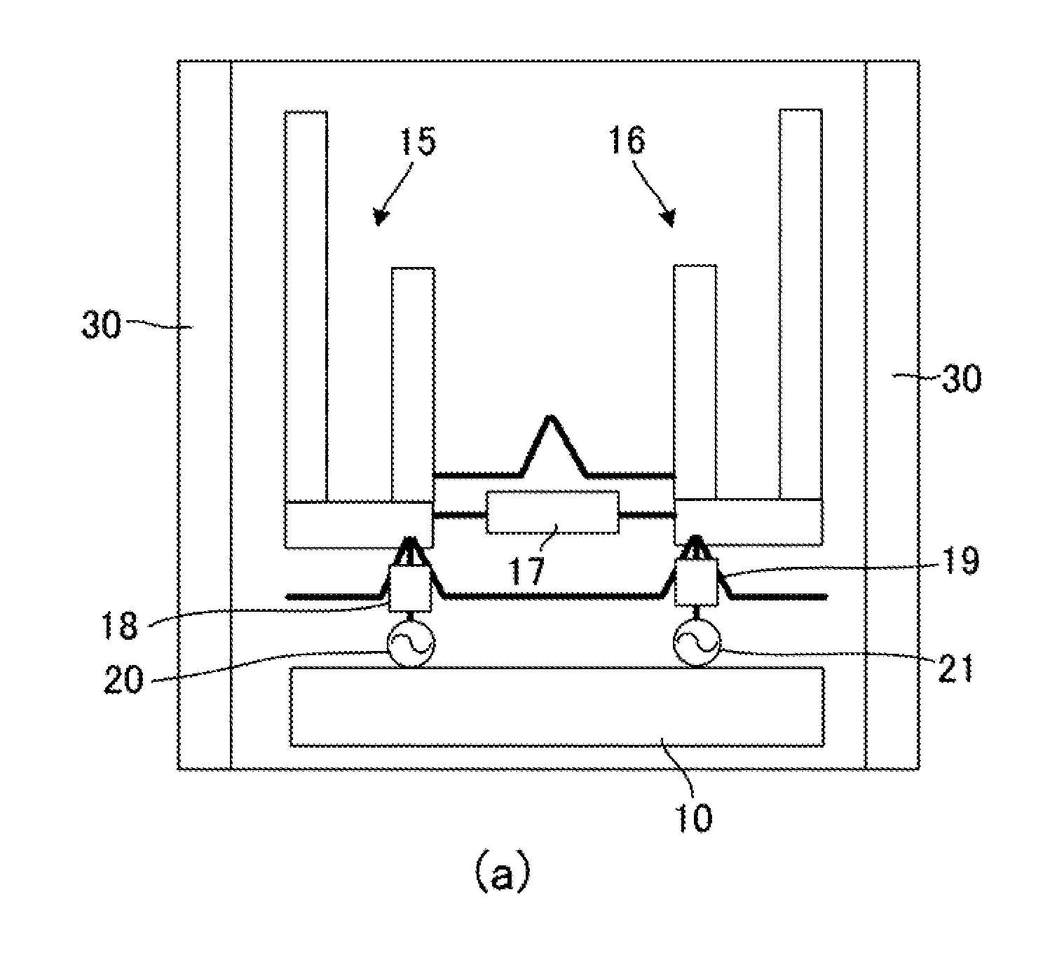
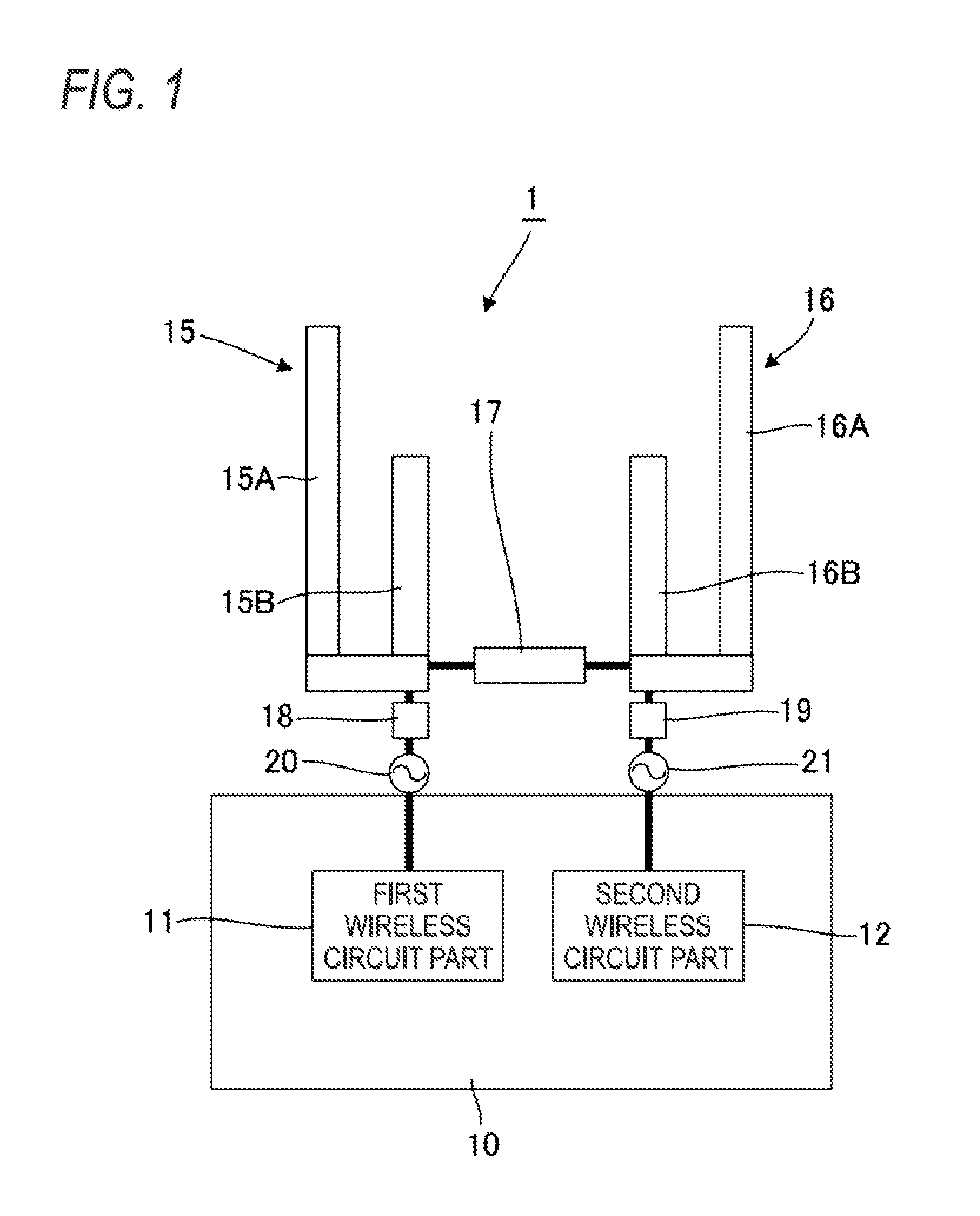
[0050]FIG. 1 is a schematic part diagram showing an antenna of an embodiment of the present invention. In the drawing, an antenna 1 of the embodiment has a ground pattern (omitted from the drawings) and also includes a circuit board 10 equipped with first and second wireless circuit parts 11 and 12, a first antenna element 15 having a branch structure, a second antenna element 16 having a branch structure, a low coupling circuit 17 interposed between the first antenna element 15 and the second antenna element 16, first and second matching parts 18 and 19, and first and second power feeding parts 20 and 21.

[0051]The first antenna element 15 is made of conductive metal and has a first branch element 15A and a second branch element 15B having a shorter electrical length than that of the first branch element 15A. The second antenna element 16 is made of conduct...


PUM


Abstract

A first antenna element is embodied in a blanched structure, and a second antenna element is embodied in a blanched structure. A low coupling circuit for increasing susceptance with an increase in frequency is interposed between the first antenna element and the second antenna element. The first antenna element and the second antenna element exhibit resonance of a Y12 component of an admittance matrix between first and second frequencies and between second and third frequencies. The first branch element and the third branch element assume a value of nearly a quarter of a resonant electrical length of the Y12 component of the admittance matrix between the first and second frequencies. The second branch element and the fourth branch element assume a value of nearly a quarter of the resonant electrical length of the Y12 component of the admittance matrix between the second and third frequencies.

Description

TECHNICAL FIELD[0001]The present invention relates to an antenna suitable for use with a multi-band-compatible mobile terminal.BACKGROUND ART[0002]In order to make recent mobile terminals conform to a bulk data transmission system, use of a plurality of antenna elements has been studied. Since 800 MHz, 1.5 GHz, 1.7 GHz, and 2.0 GHz bands are used even for a current cellular transmission method, development of an antenna capable of conforming to the multi-band has been expected. When a compact mobile terminal is equipped with a plurality of antenna elements, a high degree of isolation among antenna elements must be assured so as not to deteriorate coupling between the antenna elements. In particular, even when there are adopted measures to prevent deterioration of coupling among antenna elements, the measures will not make sense if antenna efficiency becomes worse when the mobile terminal is held by hand (in other words, when the mobile terminal is kept in hand). For these reasons, a...

Claims


Application Information

Patent Timeline
Patent Type & Authority Applications(United States)
IPC IPC(8): H01Q21/28H01Q21/00H01Q1/24H01Q1/52H01Q5/10H01Q5/321H01Q5/371H01Q9/30
CPCH01Q5/35H01Q5/371H01Q1/243H01Q1/521H01Q9/30H01Q21/28H01Q21/0006H01Q5/0058H01Q5/22H01Q5/28
Inventor SATOU, HIROSHIKOYANAGI, YOSHIOHIROBE, TAKANORIUEJIMA, HIROYUKI
Owner PANASONIC INTELLECTUAL PROPERTY MANAGEMENT CO LTD
Why Eureka
Try Eureka