Relay node device authentication mechanism

Inactive Publication Date: 2013-06-27
NEC CORP
View PDF22 Cites 28 Cited by
  • Summary
  • Abstract
  • Description
  • Claims
  • Application Information

AI Technical Summary

Benefits of technology

[0023]Relay node platform and network are able to obtain mutual authentication. Relay node platform and UICC also are able to obtain mutual authentication. The mutual authentication ensures that an UE (User Equipment)-UICC or any other fraud UICC will not be misused in a RN and also prevents to misus

Problems solved by technology

However, the AKA procedure of SAE (System Architecture Evolution)/LTE disclosed in NPL 3 is not su

Method used


Image

  • Relay node device authentication mechanism
  • Relay node device authentication mechanism
  • Relay node device authentication mechanism

Examples


Embodiment Construction

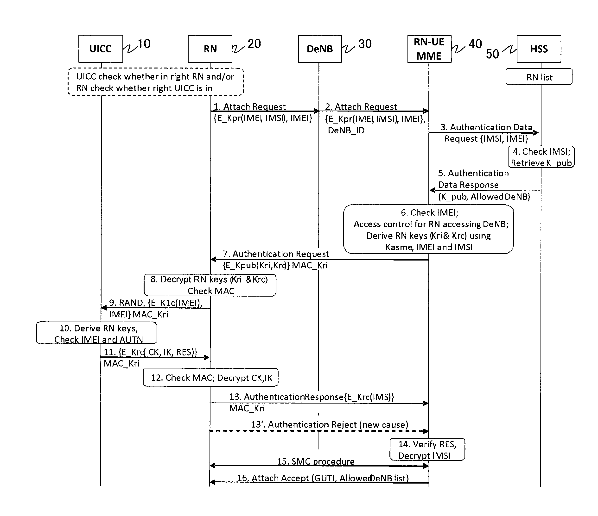
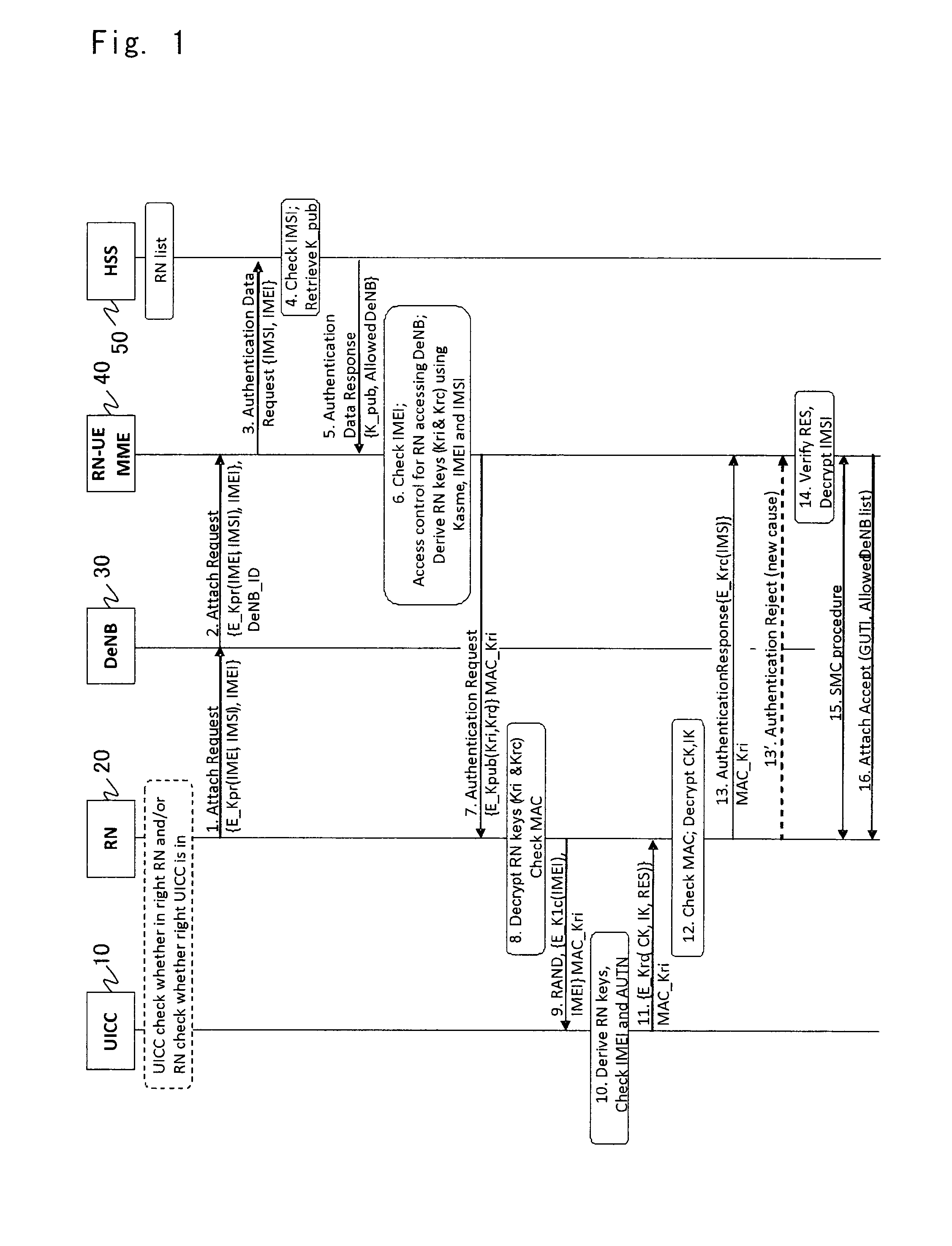
[0031]Hereafter, an exemplary embodiment of a relay node, a network node and an ICC according to the present invention, and a network system to which these nodes and ICC are applied will be described with reference to FIGS. 1 to 5. Note that the same signs are assigned to the same elements throughout the drawings, and their duplicated explanation is omitted as appropriate for clarifying the description.

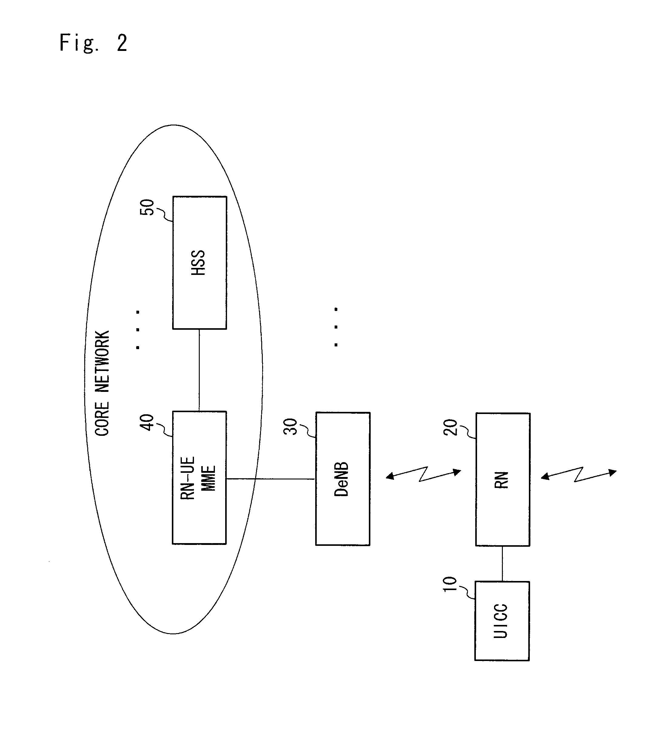
[0032]As shown in FIG. 2, the network system according to this exemplary embodiment includes a UICC10, an RN 20, a DeNB 30, an MME 40, and an HSS 50. The UICC 10 is bound to the RN 20. The RN 20 wirelessly relays traffic between a UE (not shown) and the DeNB 30. The MME 40 performs access control for the DeNB 30, by communicating with the HSS 50 if necessary. Note that configuration examples of the UICC 10, the RN 20 and the MME 40 will be described later with reference to FIGS. 3 to 5.

[0033]In this exemplary embodiment, we propose a solution for relay node authentication that provide...


PUM


Abstract

A solution of relay node authentication is proposed. The solution includes mutual authentication of relay node and relay UICC, mutual authentication of relay node and network, secure channel establishment between relay UICC and relay node. AKA procedure in TS 33.401 is re-used so that no extra NAS message is needed. IMEI is sent to network in the initial NAS message, according to which MME-RN can retrieve RN's public key from HSS, and perform access control for DeNB. MME-RN will generate a session key based on IMSI, IMEI and Kasme, and encrypt it by RN's public key and send it to RN. UICC will also generate the same key and thus RN can authenticate both UICC and network. When the key or other parameters sent between UICC and RN do not match, UICC or RN will send Authentication Reject message with a new cause to inform network.

Description

TECHNICAL FIELD[0001]A mechanism is proposed for mutual authentication between Relay Node (RN) device and network, mutual authentication and secure channel establishment between relay-Universal Integrated Circuit Card (UICC) and relay device. It provides a solution re-using Authentication and Key Agreement (AKA) procedure and initial Non-Access Strum (NAS) procedure in Non Patent Literature (NPL) 3, in order to prevent attacks (NPL 2). It prevents malicious modification or misuse of relay-UICC, relay device configuration, interception and modification of the messages between them.BACKGROUND ART[0002]The Third Generation Partnership Project's (3GPP's) Long Term Evolution (LTE)-Advanced is considering relaying for cost-effective throughput enhancement and coverage extension (see NPL 1). In the relay architecture, man-in-the-middle (MitM) attack, communication hijack and several other attacks are possible if the communication between relay-UICC (UICC will be used for relay-UICC onwards...

Claims


Application Information

Patent Timeline
IPC IPC(8): H04W12/04
CPCH04B7/155H04L63/0853H04L63/0869H04L63/123H04W12/10H04W84/047H04W88/04H04W12/04H04W12/06H04W12/041H04W12/0471H04W12/069H04W12/106H04W12/108H04W12/48
Inventor ZHANG, XIAOWEIPRASAD, ANAND RAGHAWA
Owner NEC CORP
Why Eureka
Try Eureka