Stiffener run-out

a run-out and stringer technology, applied in the field of stringer, can solve the problems of stringer run-outs that cannot be loaded, stringer run-outs that have to be terminated, stringer run-outs that can suffer cracking when loaded, etc., and achieve the effect of sufficient bending stiffness and enhanced panel strength

Active Publication Date: 2013-06-27
AIRBUS OPERATIONS LTD
View PDF6 Cites 12 Cited by
  • Summary
  • Abstract
  • Description
  • Claims
  • Application Information

AI Technical Summary

Benefits of technology

[0010]The invention is advantageous in that the fitting may have sufficient bending stiffness to minimise bending of the panel local to the stiffener foot at the run-out, which reduces the peeling force at the end of the stiffener foot and so enhances the strength in terms of the load required for crack initiation at the end of the stiffener foot. Although the bending of the panel is transferred further outboard to the outboard end of the fitting, the fitting may be fastened, and not bonded, to the panel and so there can be sufficient strength in the fasteners to resist the resulting through thickness loading.
[0012]The invention is advantageous in that the overhanging portion of the web may be used to secure the web outboard of the end of the stringer foot.
[0023]The fitting may have sufficient bending stiffness to prevent bending of the panel local to the end of the stiffener foot.
[0024]The end of the stiffener foot may have a back chamfer. The back chamfer may have a surface facing outboard and towards the panel. A resin fillet may be provided between the back chamfer and the panel. The resin fillet may substantially fill the void between the back chamfer and the panel, and may further feature a round at the outboard end of the fillet. The back chamfer may enhance the strength of the panel to stiffener joint at the outboard end of the foot.
[0026]The stiffener may have a fillet at the intersection between the stiffener web and the end of the stiffener foot. The fillet helps reduce stress concentrations.

Problems solved by technology

Stiffeners have to be terminated in certain areas due to conflict with other structural components.
The stringer run-outs can suffer cracking when loaded due to the natural offset between the stringer and the skin.
The offset causes out of plane bending, which results in tensile through-thickness loads that can cause peeling at the (tip) end of the stringer foot run-out where it attaches to the skin.

Method used


Image

  • Stiffener run-out
  • Stiffener run-out
  • Stiffener run-out

Examples


Embodiment Construction

)

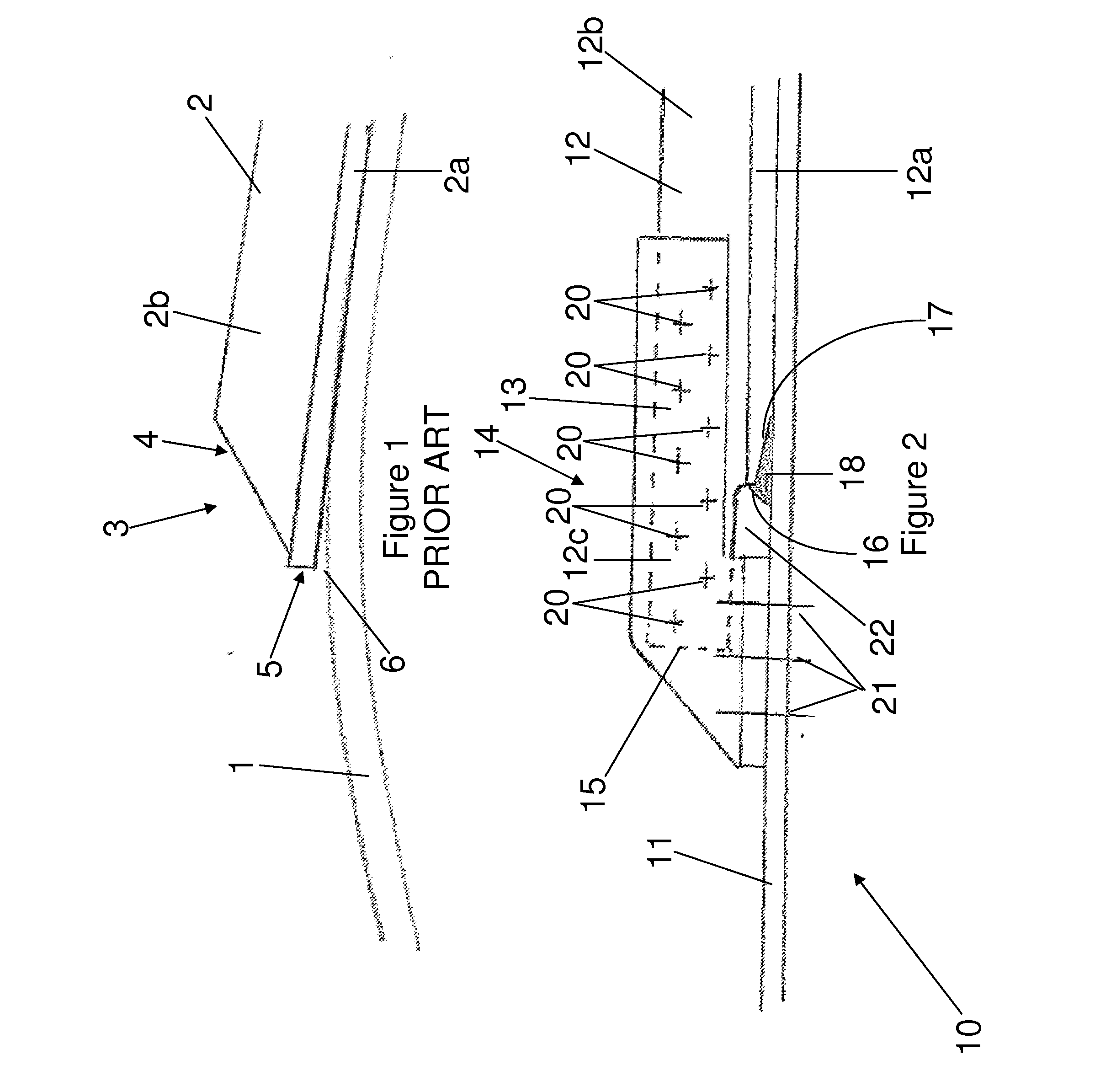
[0042]FIG. 1 illustrates a conventional stiffener reinforced panel. In this example, the panel 1 is a skin of an aircraft wingbox, and the stiffener 2 is a reinforcing longitudinal stringer. The stiffener 2 has an inverted “T” shape cross section so as to form a foot 2a and an upstanding web 2b. The stiffener 2 has a run-out region 3 at one end. In this example, the run-out region features a taper 4 of reducing web height towards the outboard end 5 of the stiffener foot 2a. FIG. 1 illustrates a side view of the stiffener reinforced panel under tensile load (exaggerated) applied in the longitudinal direction of the stiffener and shows a typical crack initiation site 6 at the outboard end 5 of the stiffener foot 2a.

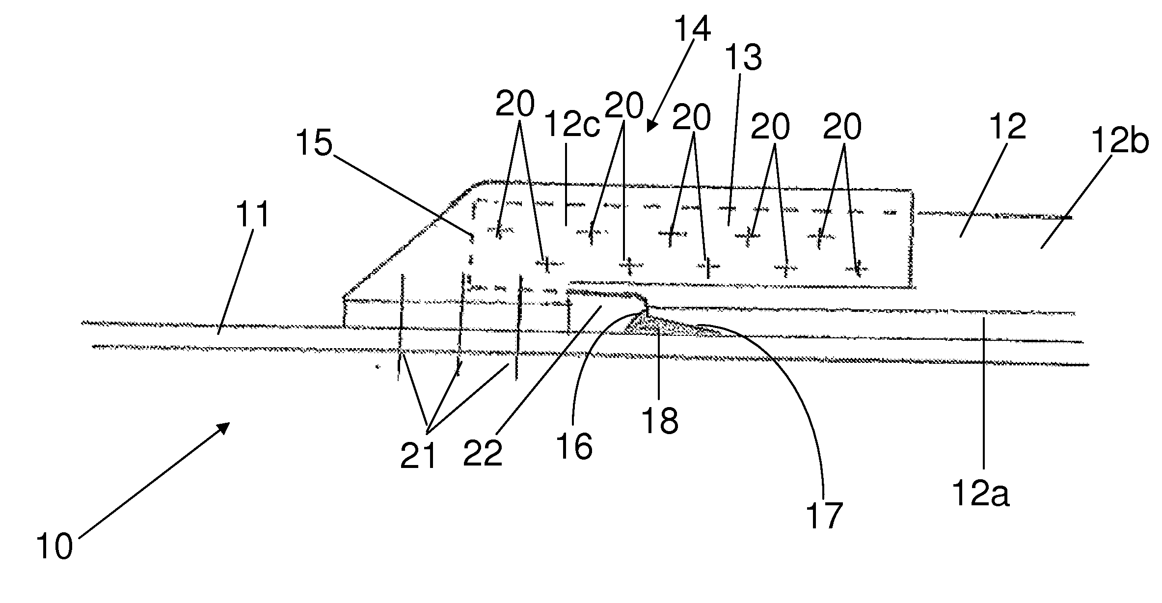
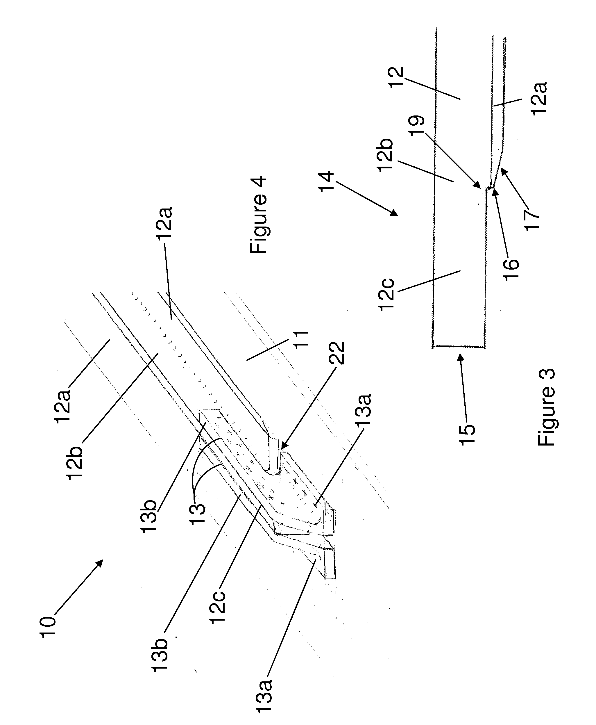
[0043]FIG. 2 illustrates a stiffener reinforced panel assembly 10 according to an embodiment of this invention. The assembly 10 includes a panel 11, a stiffener 12 and a fitting 13. In this example, the panel 11 is a skin of an aircraft wingbox and the stiffener 12 is a r...


PUM

PropertyMeasurementUnit
stress concentrationsaaaaaaaaaa
bending stiffnessaaaaaaaaaa
weightaaaaaaaaaa

Abstract

A panel assembly comprising: a panel (11); a stiffener (12) having a foot (12a), an upstanding web (12b) and a run-out region at one end; and a fitting (13), wherein the stiffener foot is bonded to the panel, and wherein the fitting is attached to the stiffener web and to the panel outboard of the end of the stiffener foot. The outboard end of the web may overhang an outboard end of the foot in the run-out region, of the stiffener.

Description

FIELD OF THE INVENTION[0001]The present invention relates to a stiffener having a run-out region; a panel assembly including a stiffener reinforced panel; a kit of parts for forming a stiffener reinforced panel; and a method of forming a stiffener reinforced panel.BACKGROUND OF THE INVENTION[0002]A thin-walled panel may be stiffened by attachment of a plurality of stiffeners, which divide the panel into a plurality of smaller and more stable sub-panels. Stiffener reinforced panels are encountered in many weight optimised structures, such as aircraft structures. For example, an aircraft wing box typically includes upper and lower covers, which comprise a skin (panel) stiffened with reinforcing longitudinal stringers (stiffeners).[0003]Stiffeners have to be terminated in certain areas due to conflict with other structural components. In the case of an aircraft wing box, the stiffeners typically have to be terminated at, e.g. the wing root, the wing tip, access holes etc. At the stiffe...

Claims


Application Information

Patent Timeline
Patent Type & Authority Applications(United States)
IPC IPC(8): B64C1/06B23P19/00
CPCB64C3/182B64C3/26B64C1/06Y10T428/24174B23P19/00Y10T29/49616Y10T428/24008B64C1/064B64C3/18
Inventor GAITONDE, MARTINCOSENTINO, ENZO
Owner AIRBUS OPERATIONS LTD
Why Eureka
Try Eureka