
Patient Specific Implants and Instrumentation For Patellar Prostheses

a technology for patellar arthroplasty and patient-specific implants, which is applied in the field of patient-specific implants and instruments for patellar arthroplasty, can solve the problems of insufficient removal of patellar fracture, and inability to remove all areas of diseased cartilag

Inactive Publication Date: 2013-06-27
RIES MICHAEL D DR
View PDF4 Cites 46 Cited by
  • Summary
  • Abstract
  • Description
  • Claims
  • Application Information

AI Technical Summary

Benefits of technology

The patent text describes a system, methods, and instrumentation for total knee arthroplasty that includes implantable patellar prostheses, instrumentation for patellar reaming and resection, and methods for patellar arthroplasty. The technical effects of this patent include the development of implants and instrumentation that conserve bone volume while also allowing for the removal of all areas of diseased cartilage, as well as the use of multi-planar implants and methods for preparing the patella that provide better resistance to shear loads, are more resistant to loosening and migration, and better overall coverage of the articular surface.

Problems solved by technology

Alternatively, some onlay implants are smaller than the exposed area and leave a portion of the cut bone exposed, which may create problems with soft tissue ingrowth.
Furthermore, onlay patellar implants may be more prone to migrating or loosening then inset implants.
The reaming step used to prepare the patella for the onlay implant also does little to conserve the amount of bone volume remaining in the patella, which can lead to complications such as patellar fracture.
While an inset “button” implant may completely cover the resurfaced portion of the bone, the smaller prosthesis area may not sufficiently remove all areas of diseased cartilage and the patient may be left with pathology.
A single flat anchoring surface may not provide resistance to shear loads, and may therefore be more prone to loosening and migration.

Method used


Image

  • Patient Specific Implants and Instrumentation For Patellar Prostheses
  • Patient Specific Implants and Instrumentation For Patellar Prostheses
  • Patient Specific Implants and Instrumentation For Patellar Prostheses

Examples


Embodiment Construction

[0049]The present disclosure relates to patellar implants and instrumentation and methods for preparation and implantation of these devices. Those of skill in the art will recognize that the following description is merely illustrative of the principles of the disclosure, which may be applied in various ways to provide many different alternative embodiments. This description is made for the purpose of illustrating the general principles of this invention and is not meant to limit the inventive concepts in the appended claims. While the present disclosure is made in the context of total knee arthroplasty for the purposes of illustrating the concepts of the design, it is contemplated that the present design and / or variations thereof may be suited to applications outside the field of total knee arthroplasty. For example, the present design and / or variations thereof may be suited to applications in knee hemiarthroplasty, patellar resurfacing alone, ankle arthroplasty, or other surgical ...


PUM


Abstract

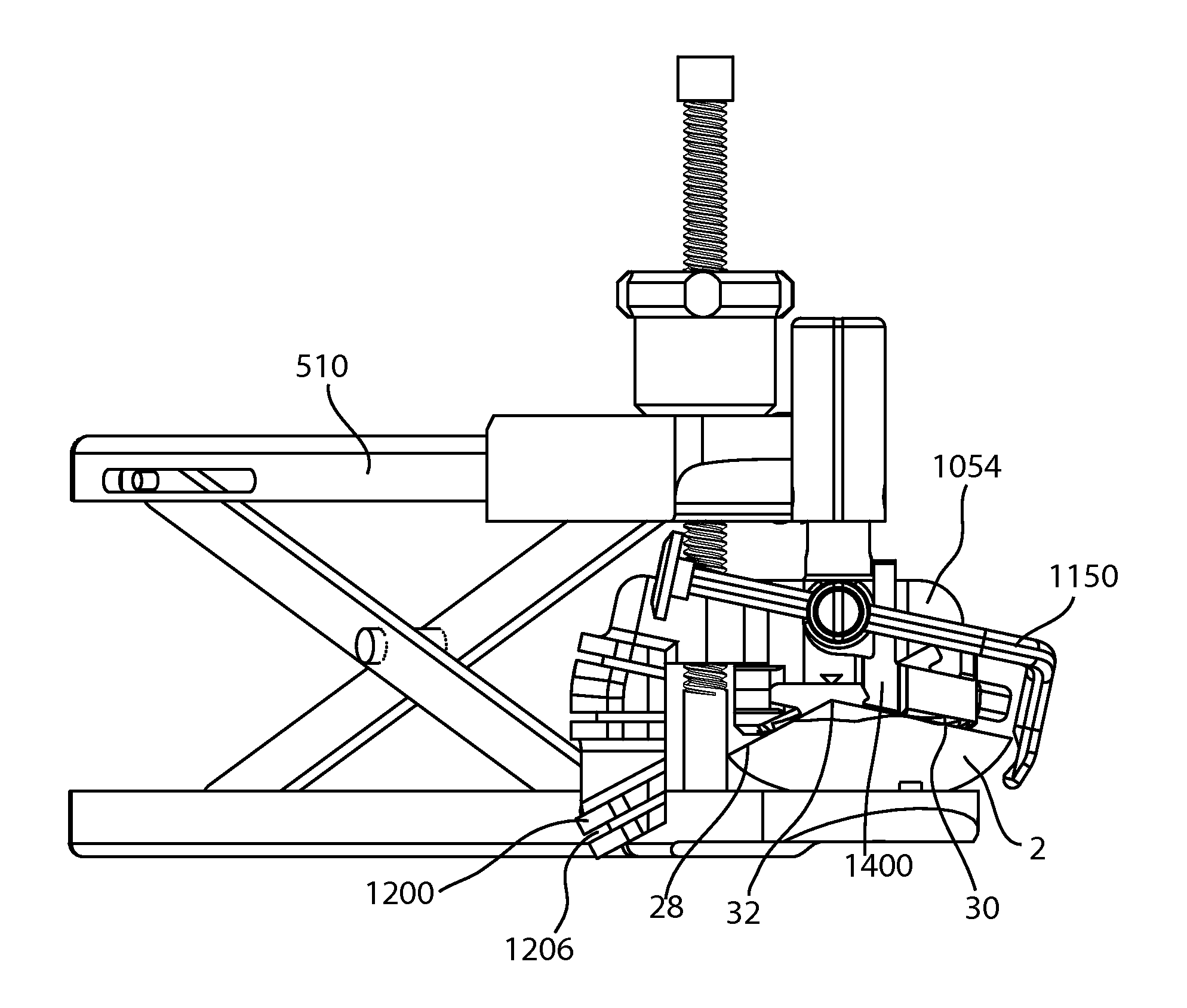
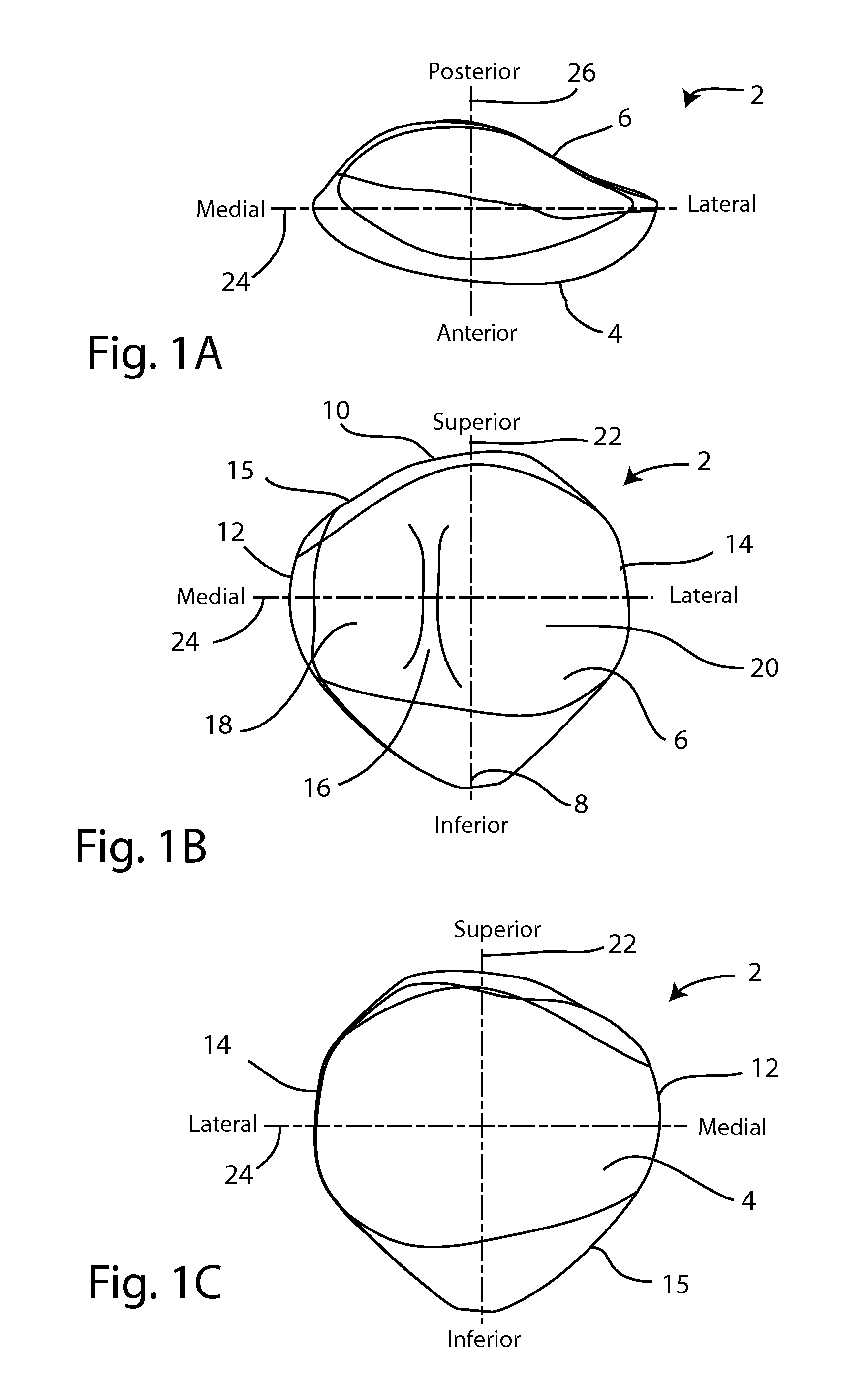
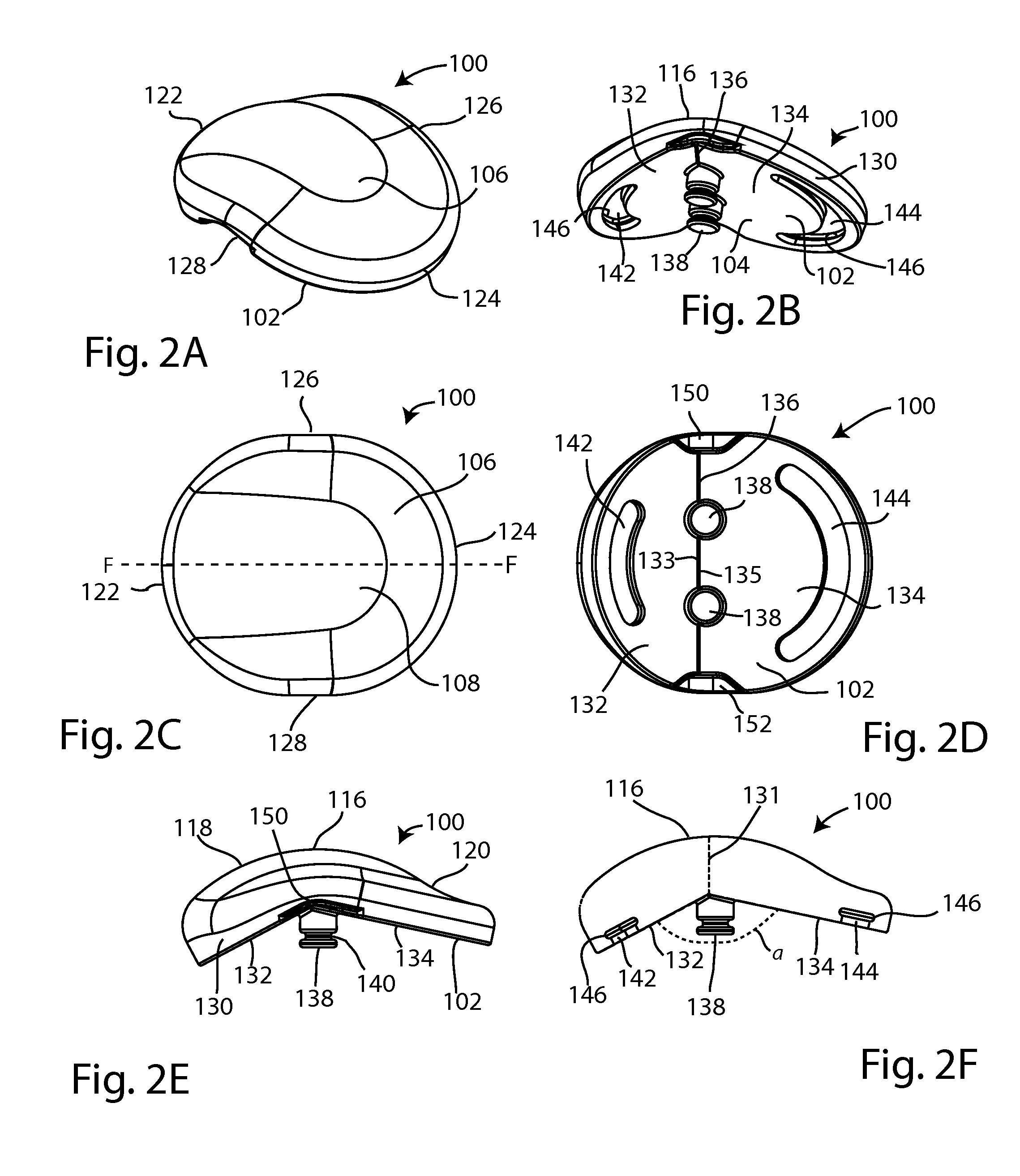
Patient specific implants and instrumentation for replacing a portion of a patella. Methods for producing patient specific implants and instrumentation include conducting imaging studies of the patient's native patella, deriving measurements of the patella and surrounding soft tissues from the imaging studies, manufacturing customized implants and instrumentation specific to the derived measurements, and implanting a customized implant using the customized instrumentation. Patient specific instrumentation includes: a patellar clamp ring, an anterior clamp, a restraining arm, a posterior clamping surface, a dual bore reaming collet, a reamer, a reaming depth gauge, and a resection cutting guide. Patient specific portions of a patellar implant include: topography of the posterior articular surface, facet angle, shape and dimensions of the anterior attachment surface, implant length, implant width, implant thickness and the outer perimeter shape of the implant.

Description

CROSS-REFERENCE TO RELATED APPLICATIONS[0001]This application is a non-provisional of:[0002]pending U.S. Provisional Patent Application No. 61 / 596,104, filed Feb. 7, 2012, which carries Applicant's docket No. MDR-15 PROV, and is entitled PATIENT SPECIFIC IMPLANTS AND INSTRUMENTATION FOR PATELLAR PROSTHESES.[0003]This application is also a continuation-in-part of:[0004]pending U.S. patent application Ser. No. 13 / 367,278, filed Feb. 6, 2012, which carries Applicant's docket No. MDR-13, and is entitled PATELLAR PROSTHESES AND INSTRUMENTATION, which application is a non-provisional of:[0005]U.S. Provisional Patent Application No. 61 / 442,661, filed Feb. 14, 2011, which carries Applicant's docket No. MDR-12 PROV, and is entitled ANATOMIC PATELLAR PROSTHESIS; and[0006]U.S. Provisional Patent Application No. 61 / 479,173, filed Apr. 26, 2011, which carries Applicant's docket No. MDR-13 PROV, and is entitled INSTRUMENTS AND METHODS FOR MULTI-PLANAR PATELLAR PROSTHESES; and[0007]U.S. Provisiona...

Claims


Application Information

Patent Timeline
Patent Type & Authority Applications(United States)
IPC IPC(8): A61B17/88A61B17/16
CPCA61B17/8863A61B17/1677A61B2019/462A61B17/1767A61B17/158A61F2/3877A61B2090/062
Inventor RIES, MICHAEL D.RINDAL, BJORN N.BUTTERS, JOSHUA A.SLATER, NICHOLAS
Owner RIES MICHAEL D DR
Learn More