Fluid regulating valve

a technology of regulating valves and fluids, applied in the field of regulating valves, can solve the problems of insufficient water storage, inconvenience to people's lives, and significant decrease in rainfall, and achieve the effects of simple structure, high reliability, and few components

Inactive Publication Date: 2013-07-04
METAL INDS RES & DEV CENT
View PDF5 Cites 8 Cited by
  • Summary
  • Abstract
  • Description
  • Claims
  • Application Information

AI Technical Summary

Benefits of technology

[0007]An objective of the present invention is to provide a fluid regulating valve, whose structure is tolerant to damages in long-term usage. Thereby, the fluid regulating valve according to the present invention has high reliability.
[0008]Another objective of the present invention is to provide a fluid regulating valve, whose structure is simple with few components. Thereby, the fluid regulating valve according to the present invention is easy for assembling and modularization,
[0009]Still another objective of the present invention is to provide a fluid regulating valve, which can regulate the flow rate of fluid according to the fluid pressure and control the flow rate of the fluid supplied by the fluid regulating valve to be within a predetermined range whatever the fluid pressure is.
[0010]For achieving the objectives described above, the fluid regulating valve provided by the present invention comprises a housing, a flow regulating member, and a gap controlling member. The housing has an inlet and a carrying part, where the carrying part forms a first outlet. The flow regulating member is disposed in the housing and located between the inlet and the first outlet for transferring a fluid pressure of a fluid. The gap controlling member is an elastic element and is located in the housing. The gap controlling member is adjacent to and between the carrying part and the flow regulating member for regulating the gap between the carrying part and the flow regulating member. Besides, the inlet and the first outlet connect with the gap. The fluid flows into the housing via the inlet and into the gap by transferring the flow regulating member, and then flows out from the first outlet. The fluid pressure of the fluid is exerted on the gap controlling member through the flow regulating member. The gap controlling member is then used for adjusting the size of the gap, and thus controlling the flow rate of the fluid out of the first outlet via the gap.

Problems solved by technology

In Taiwan, long-term lack of rains resulted in significant decrease in rainfall.
According to the official statistics, over a half of domestic reservoirs encounter the silt problem and leading to insufficient water storage.
Consequently, the policy of water rationing has to be adopted in Taiwan, which will impose inconvenience to people's lives as well bringing serious loss to industrial development.
As a result, the water usage in the area is relatively higher, leading to high expenses of the users in this area.
In addition, imperceptibly, water tends to be wasted.
Nonetheless, during the modulating process, the control lip end is likely to crack because it modulates its angles frequently.
When a heated fluid flows into the insertion part for modulating its flow rate, the damaging rate of the insertion part will be accelerated.
Moreover, as the control lip end is struck frequently by high-speed fluids, regular vibration occurs owing to pressure difference or uneven pressure on the control lip end.
Consequently, the control lip end is prone to breakage or tear damages.

Method used


Image

  • Fluid regulating valve
  • Fluid regulating valve
  • Fluid regulating valve

Examples


first embodiment

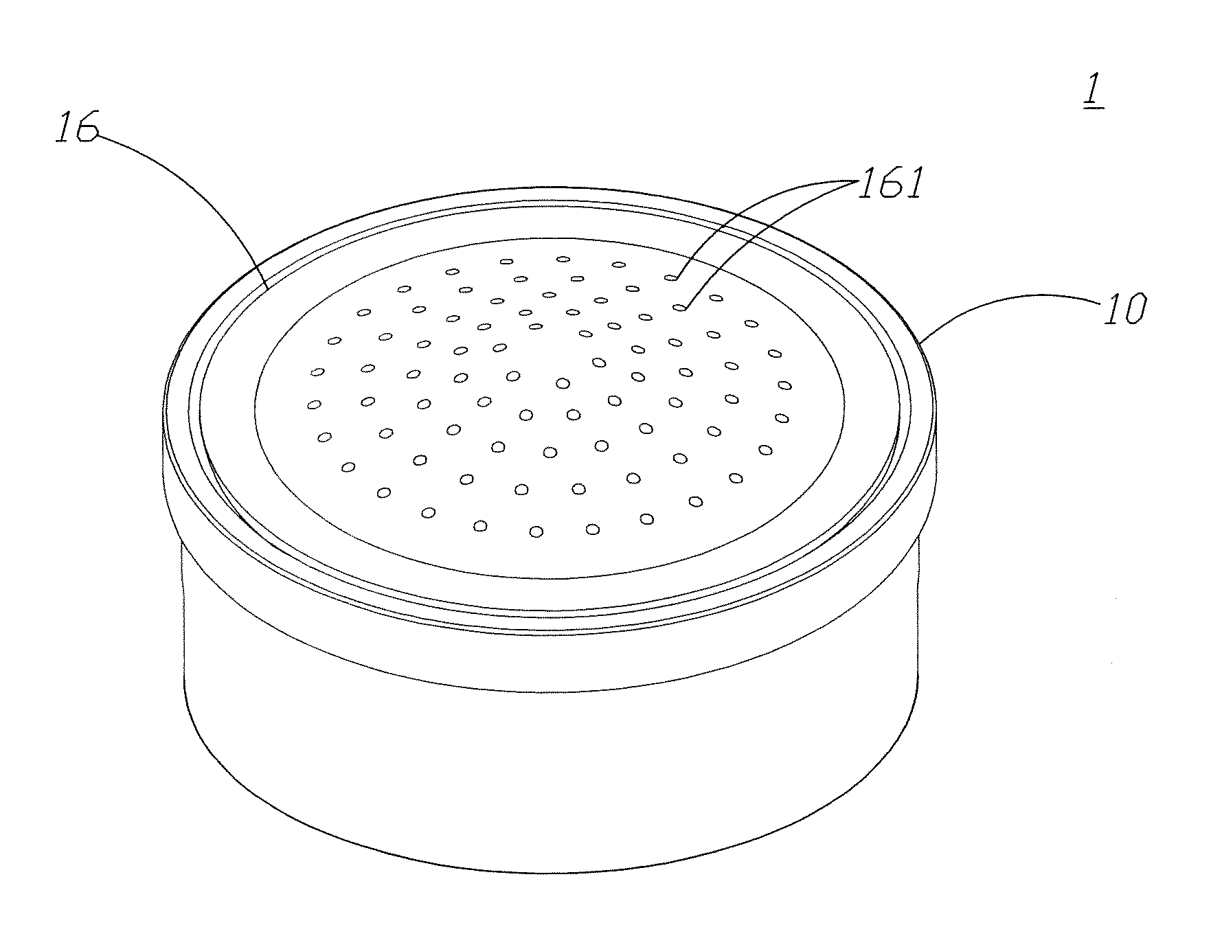
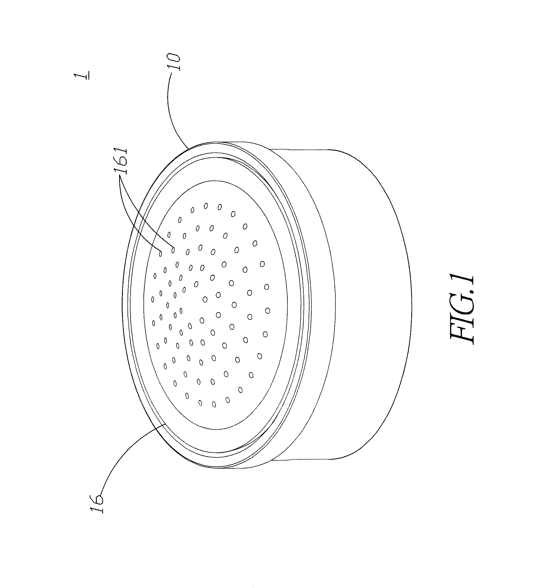
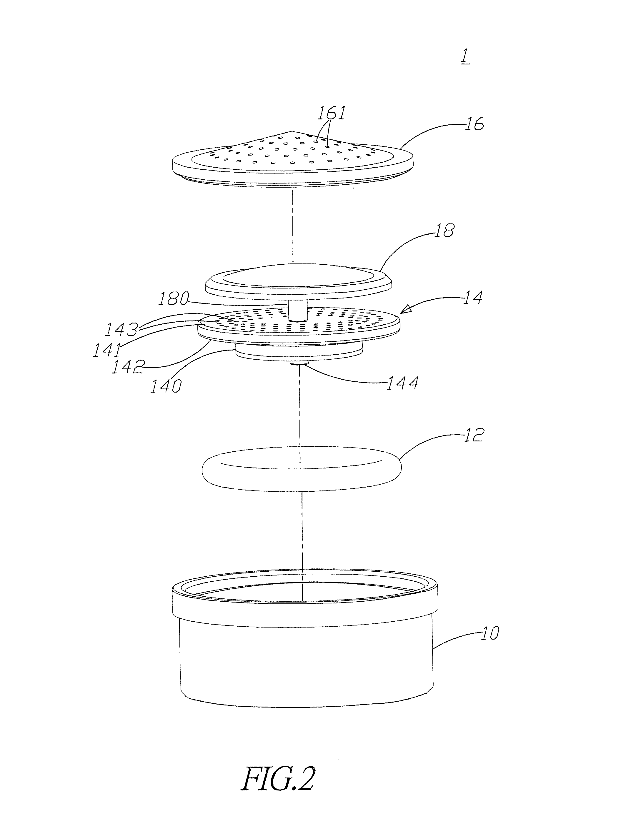
[0024]FIGS. 1, 2, and 3 show three-dimensional, exploded, and partial cross-sectional views according to the present invention. As shown in the figures, the fluid regulating valve 1 according to the present invention at least comprises a housing 10, a gap controlling member 12, and a flow regulating member 14. The housing 10 has a carrying part 101 and a surrounding sidewall 102. The surrounding sidewall 102 surrounds the circumference of the carrying part 101 and forms a hollow body. According to an embodiment of the present invention, the surrounding sidewall 102 and the carrying part 101 are further formed integrally. The top of the surrounding sidewall 102 is an opening, which forms an inlet 103. In addition, a first outlet 104 and a second outlet 105 are formed on the carrying part 101.

[0025]Refer to FIG. 3. The flow regulating member 14 is disposed in the housing 10 and located between the inlet 103 and the first and second outlets 104, 105 for pass a fluid pressure of a fluid...

third embodiment

[0051] the fluid flowing from the first outlet 104 will drain off from the through hole 1012 connecting with the first outlet 104 (as shown in FIG. 8). The first outlet 104 according to the present embodiment is formed on the carrying part 101 between the first channel 143 and the through hole 1012. The first outlet 104 according to the present embodiment is a hole penetrating the carrying part 101 of the housing 10 and not connecting with the through hole 1012 of the carrying part 101. When there is a gap between the blocking part 140 of the flow regulating member 14 and the carrying part 101, the fluid will flow in via the first channel 143, to the first outlet 104 by way of the gap, and drain off. The fluid will not converge with the fluid from the second channel 147 of the flow regulating member 14.

[0052]To sum up, the present invention provides a fluid regulating valve, which can regulate the flow rate of the fluid according to the fluid pressure. Thereby, as the fluid pressure...


PUM


Abstract

The present invention relates to fluid regulating valve, comprising a housing, a flow regulating member, and a gap controlling member. The housing has an inlet and a carrying part having a first outlet. The gap controlling member is located between the flow regulating member and the carrying part for regulating the gap between the carrying part and the flow regulating member. Fluid flows into the housing via the inlet, flows into the gap via the flow regulating member, drains off from the first outlet, and the fluid pressure of the fluid exerts pressure on the gap controlling member via the flow regulating member for controlling the flow rate of the fluid draining off the first outlet via the gap within a predetermined range by adjusting gap size using said gap controlling member. The fluid regulating valve according to the present invention is tolerant to damages in long-term usage.

Description

FIELD OF THE INVENTION[0001]The present invention relates generally to a regulating valve, and particularly to a fluid regulating valve.BACKGROUND OF THE INVENTION[0002]Owing to the global warming effect, extraordinary phenomena of extreme weather occur in various countries. For example, large-area droughts happen in Asia. Farther, the American area appears floods. In addition, Taiwan is not exempt from the disasters. In Taiwan, long-term lack of rains resulted in significant decrease in rainfall. According to the official statistics, over a half of domestic reservoirs encounter the silt problem and leading to insufficient water storage. Consequently, the policy of water rationing has to be adopted in Taiwan, which will impose inconvenience to people's lives as well bringing serious loss to industrial development. Thereby, how to reserve and spare water resources has become an important subject.[0003]Besides, due to different hydraulic pressure in different areas, the water usage in...

Claims


Application Information

Patent Timeline
Patent Type & Authority Applications(United States)
IPC IPC(8): F16K31/12
CPCF16K31/12F16K17/28F16K17/34G05D7/0133E03C1/08E03C1/104B05B1/3006B05B12/088
Inventor LIN, TIN-KAIHUANG, JYUNG-YINGLIN, DA-YU
Owner METAL INDS RES & DEV CENT
Why Eureka
Try Eureka