Check patentability & draft patents in minutes with Patsnap Eureka AI!

Spherical Magnet

a magnet and spherical technology, applied in the field of magnet improvement, can solve the problems of limited temperature gradient and heat transfer ability into and out of containers, relatively slow wheel turning, and limited engine power output,

Active Publication Date: 2013-07-04
MILLER MICHAEL
View PDF0 Cites 0 Cited by
  • Summary
  • Abstract
  • Description
  • Claims
  • Application Information

AI Technical Summary

Benefits of technology

The use of active heat exchangers increases the heat transfer rate, enabling higher power output and efficiency by recapturing energy, allowing for independent rotation of container pairs and improved mechanical work production.

Problems solved by technology

The wheel turns relatively slowly, but produces enormous torque.
For the passively heated wheels and containers created from small tanks or lengths of cylindrical pipe, the temperature gradient and ability to transfer heat into and out of the containers is limited, limiting the power output of the engine.
In addition to the heat transfer rate limitations, conventional arrangements of the wheel fix each container into a given position along the wheel.

Method used


Image

  • Spherical Magnet
  • Spherical Magnet
  • Spherical Magnet

Examples


Embodiment Construction

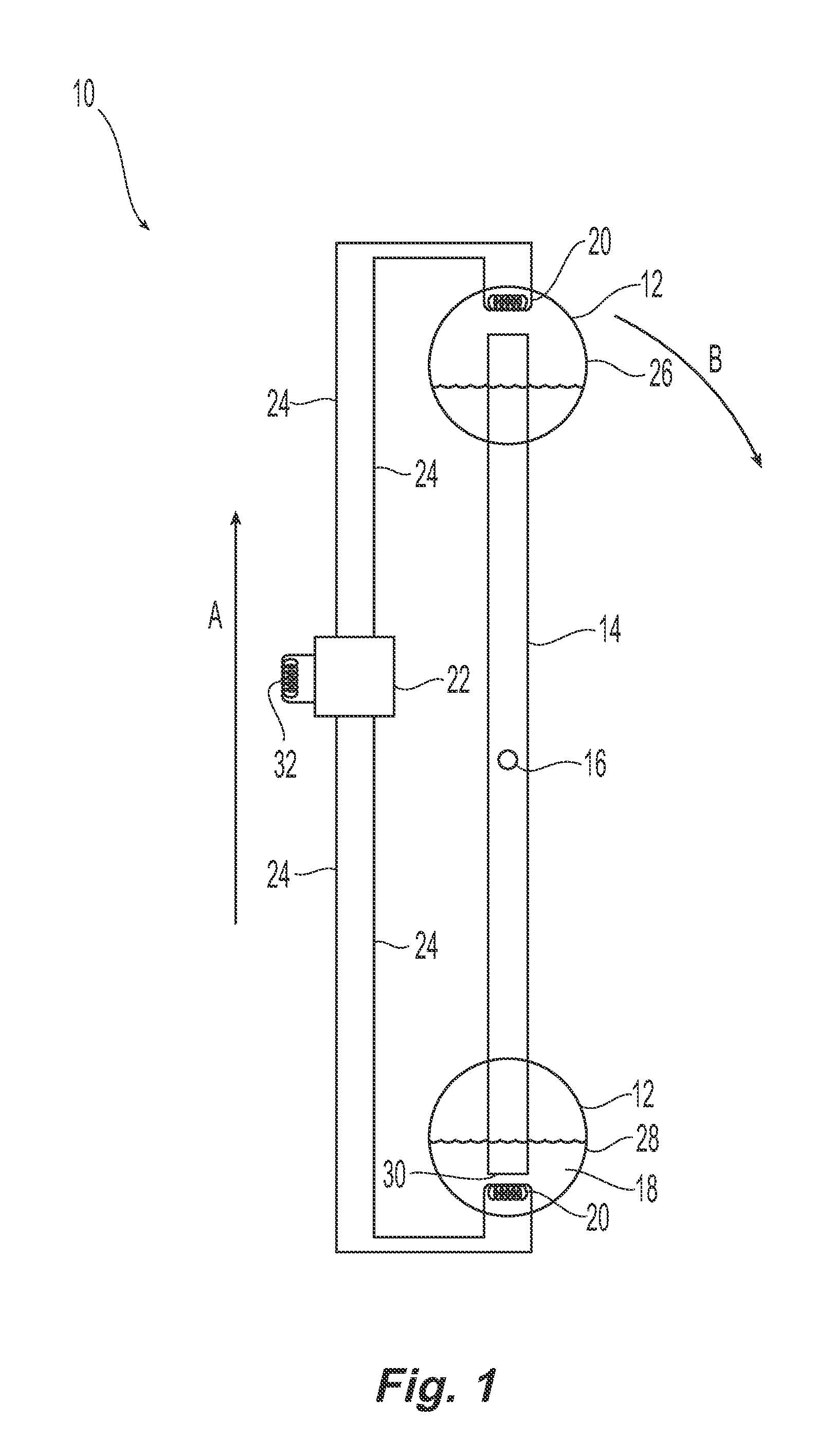
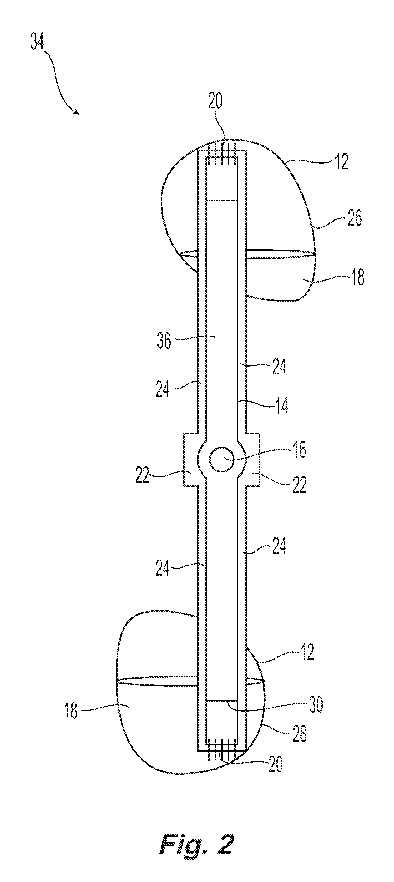
[0030]Systems and methods in accordance with exemplary embodiments of the present invention incorporate active heat exchangers, for example heat pumps, into engines that use the expansion of low-boiling point liquids in a sealed rotational device to produce useful mechanical work. The active heat exchanger is used to move heat from the ambient environment into the low-boiling point liquids contained within the engine. In an embodiment where the active heat exchanger is a heat pump, the evaporation and condensation of a refrigerant are used to transfer heat into, and if desired out of, the low-boiling point liquids of the engine. The operation of heat pumps generally is known in the art. The heat pump consumes energy, for example electrical energy, to power an electric compressor. However, the heat pump can move or transfer more energy than it consumes. For example, the consumption of one unit of electrical energy by the heat pump results in the transfer of three, four or five units ...


PUM

PropertyMeasurementUnit
temperatureaaaaaaaaaa
sizeaaaaaaaaaa
widthaaaaaaaaaa

Abstract

A spherical magnet is formed as a hollow sphere having a fluid tight outer surface of a first magnetic pole and an inner surface having a second magnetic pole that is magnetically opposite the first pole. A plurality of individual thin flexible rectangular plate magnets are arranged as a continuous outer layer of the spherical magnet. Each individual plate magnet has four sides, an inner magnetic portion and an outer non-magnetic portion that extends around all four sides of the magnetic portion. Each inner magnetic portion includes a first face disposed on the outer surface and having the first pole and a second face opposite the first face, disposed on the inner surface and having the second pole.

Description

CROSS-REFERENCE TO RELATED APPLICATIONS[0001]The present application is a divisional of co-pending U.S. patent application Ser. No. 12 / 711,173 filed Feb. 23, 2010, which was a continuation-in-part of U.S. patent application Ser. No. 11 / 676,416 filed Feb. 19, 2007, which issued as U.S. Pat. No. 7,694,515 on Apr. 13, 2010. The entire disclosures of those applications are incorporated herein by reference.FIELD OF THE INVENTION[0002]The present invention is directed to improvements in magnets.BACKGROUND OF THE INVENTION[0003]A slow moving, high torque engine or generator is known that operates on a very small temperature differential. This engine is commonly referred to as a Minto Wheel after its inventor Wallace Minto. The engine is arranged as a wheel that contains a series of sealed containers. The sealed containers are placed around the rim of the wheel and are aligned as diametrically opposed pairs. Each diametrically opposed pair is in fluid connection through a tube. The wheel ro...

Claims


Application Information

Patent Timeline
Patent Type & Authority Applications(United States)
IPC IPC(8): H01F7/02
CPCF01K25/10H01F7/0221H01F7/02F01K27/00
Inventor MILLER, MICHAEL
Owner MILLER MICHAEL
Features
  • R&D
  • Intellectual Property
  • Life Sciences
  • Materials
  • Tech Scout
  • Unparalleled Data Quality
  • Higher Quality Content
  • 60% Fewer Hallucinations
Learn More