
Computer system and communication method in computer system

a computer system and communication method technology, applied in the field of computer system and communication method in the computer system, can solve the problems of consumption of the whole system resources (the number of flow entries), and achieve the effect of reducing the consumption of the resources of the whole computer system using openflow techniqu

Active Publication Date: 2013-07-04
NEC CORP
View PDF3 Cites 61 Cited by
  • Summary
  • Abstract
  • Description
  • Claims
  • Application Information

AI Technical Summary

Benefits of technology

The present invention helps reduce the use of computer system resources when using the OpenFlow technique.

Problems solved by technology

Therefore, when using the OpenFlow technique, there is a fear that resources of the whole system (the number of flow entries) are consumed greatly.

Method used


Image

  • Computer system and communication method in computer system
  • Computer system and communication method in computer system
  • Computer system and communication method in computer system

Examples


Embodiment Construction

[0036]Hereinafter, exemplary embodiments of the present invention will be described with reference to attached drawings. In the drawings, the same or similar reference numerals assigned to the same or similar components.

(Configuration of Computer System)

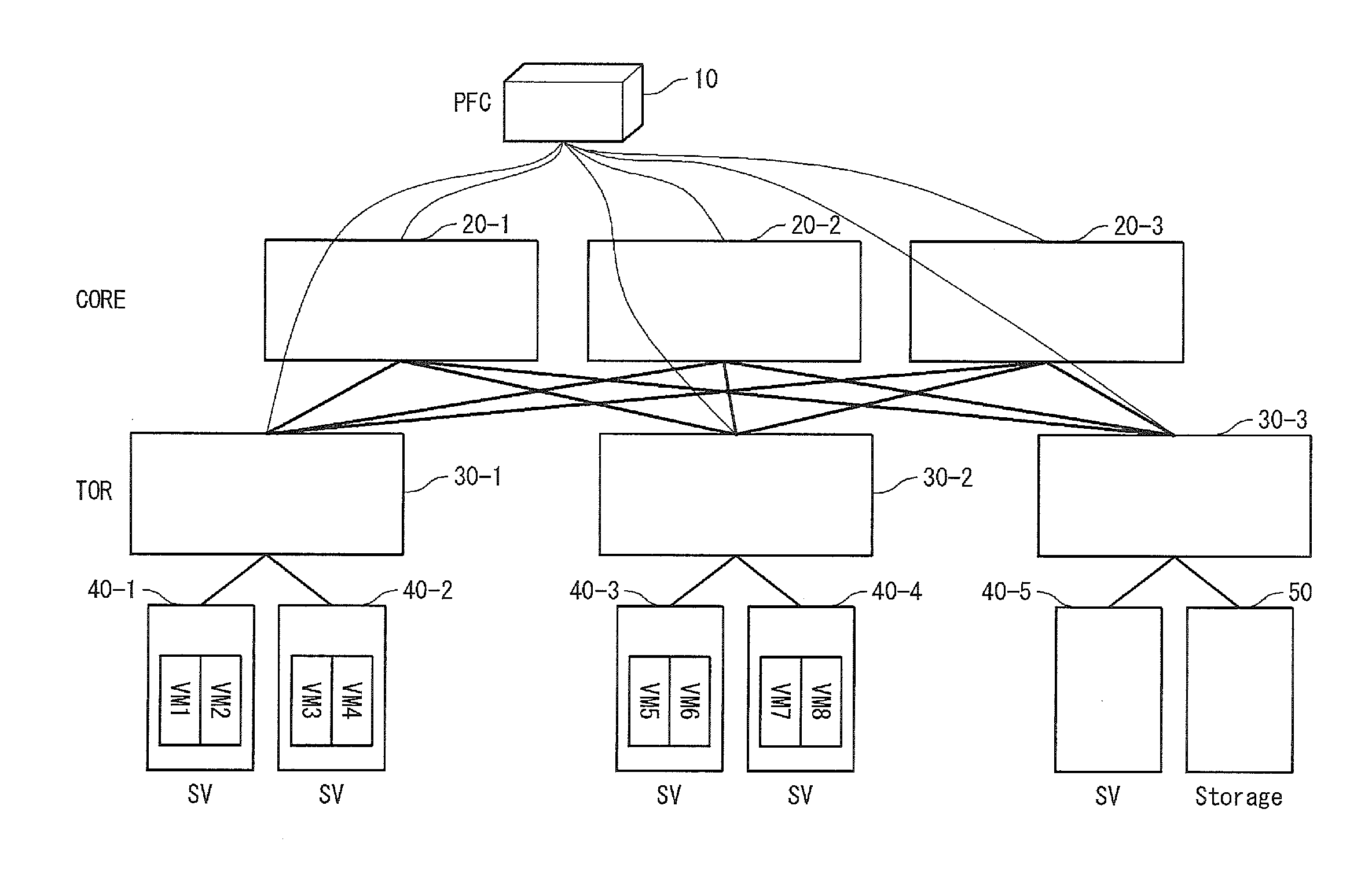
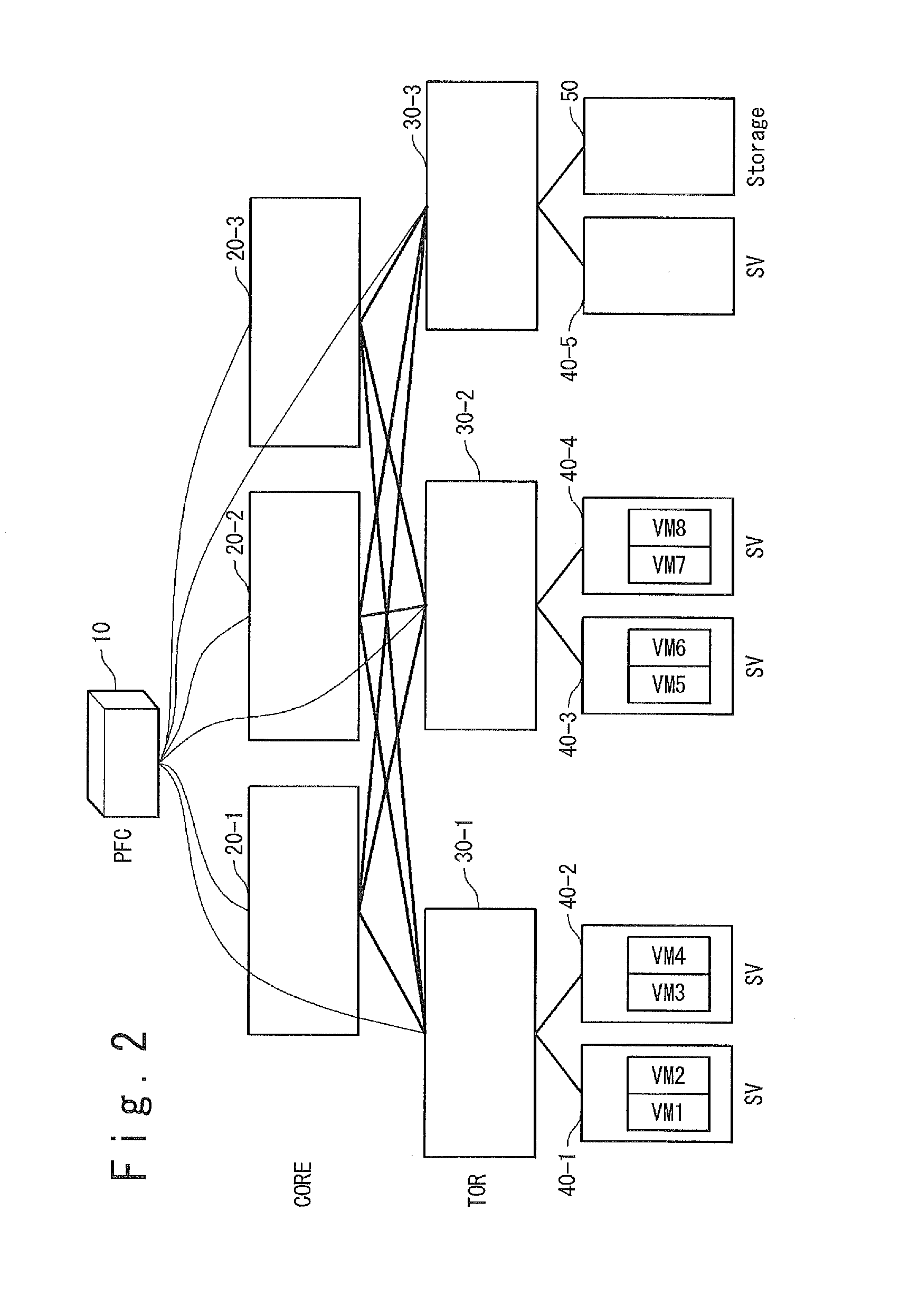
[0037]Referring to FIG. 2, a configuration of a computer system according to the present invention will be described. FIG. 2 is a diagram showing an example of the configuration of the computer system according to the present invention. The computer system according to the present invention includes a programmable flow controller 10 (hereinafter, to be referred to as a PFC 10), a plurality of programmable flow switches 20-1 to 20-3 and 30-1 to 30-3 (hereinafter, to be referred to as PFSs 20-1 to 20-3 and 30-1 and 30-3), physical servers 40-1 to 40-5 (hereinafter, to be referred to as SVs 40-1 to 40-5), and a storage 50, which are connected through a communication network. Meanwhile, when the PFSs 20-1 to 20-3 and 30-1 to 30-3 are des...


PUM


Abstract

A computer system of the present invention includes a controller which sets a flow entry to each of a plurality of switches before a packet is forwarded from a plurality of nodes, and each of switches which transfers a reception packet which contains a destination address defined in the flow entry, to a destination node defined in the flow entry regardless of a transmission source address of the reception packet.

Description

TECHNICAL FIELD[0001]The present invention relates to a computer system and a communication method in the computer system, and especially, relates to a computer system using an OpenFlow technique.BACKGROUND ART[0002]In a communication using the Ethernet (Registered trademark), flexibility of a physical link which can be used in a network is lost due to Spanning Tree Protocol (STP), and accordingly a multi-path communication has become gradually impossible.[0003]In order to solve the problem, a route control by the OpenFlow is proposed (reference to Non-Patent Literature 1). A computer system using the OpenFlow technique is disclosed, for example, in JP 2003-229913A (Patent Literature 1). A network switch corresponding to the technique (hereinafter, to be referred to as a programmable flow switch (PFS)) retains detail information such as a protocol type and a port number in a flow table, and can control a flow. It should be noted that the PFS is also referred to as an OpenFlow switch...

Claims


Application Information

Patent Timeline
Patent Type & Authority Applications(United States)
IPC IPC(8): H04L12/56H04L45/74H04L45/24H04L45/42
CPCH04L47/12H04L45/66H04L12/462H04L45/42H04L45/38H04L45/24H04L61/103H04L12/44H04L45/54
Inventor TAKASHIMA, MASANORIKASE, TOMOHIROUENO, HIROSHIMASUDA, TAKAHISAYUN, SUHUN
Owner NEC CORP
Learn More