Firearm with dual charging handles

a charging handle and firearm technology, applied in the field of firearms, can solve the problems of difficulty in operation of the top-mounted charging handle, the time between failures, and the size of the charging handle for use by someone wearing gloves and protective clothing, so as to improve the appreciation of the contribution to the art

Inactive Publication Date: 2013-07-11
GANGL JOHN P +1
View PDF6 Cites 79 Cited by
  • Summary
  • Abstract
  • Description
  • Claims
  • Application Information

AI Technical Summary

Benefits of technology

[0017]There has thus been outlined, rather broadly, the more important features of the invention in order that the detailed descrip

Problems solved by technology

One issue is the mean time between failures due to metal fatigue.
Another issue is whether the charging handle is sufficiently large for use by someone wearing heavy gloves and protective clothing.
However, a top-mounted charging handle is difficult to ope

Method used


Image

  • Firearm with dual charging handles
  • Firearm with dual charging handles
  • Firearm with dual charging handles

Examples


Embodiment Construction

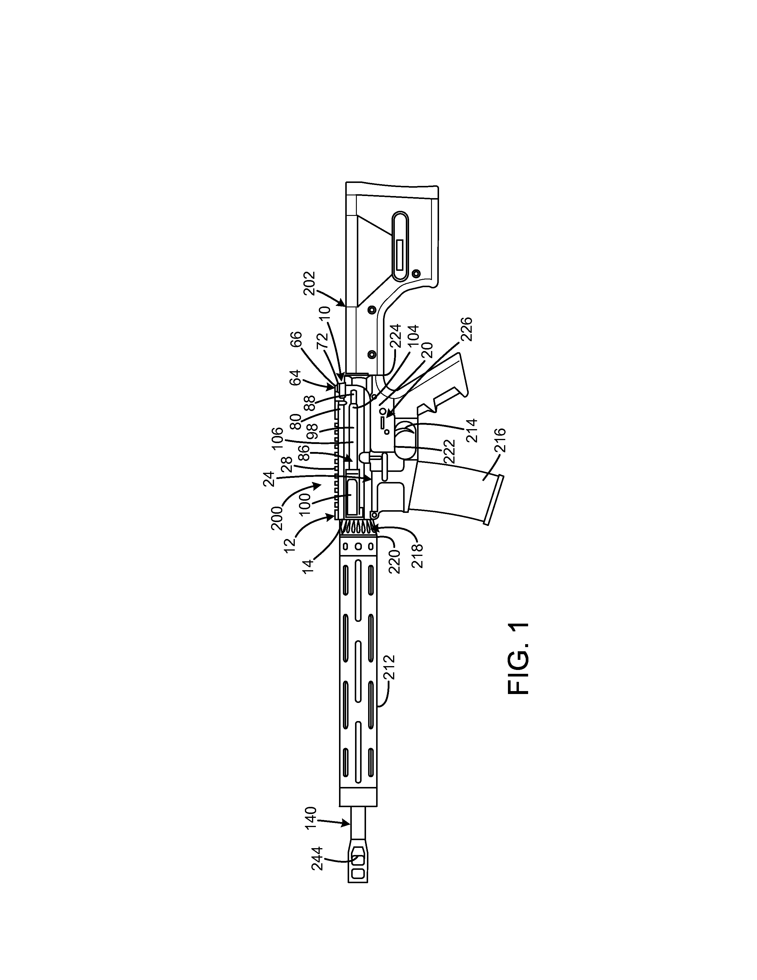
[0032]An embodiment of the firearm with dual charging handles of the present invention is shown and generally designated by the reference numeral 200.

[0033]FIG. 1 illustrates the improved firearm with dual charging handles 200 of the present invention. More particularly, the firearm is a rifle having an upper receiver assembly 10 with a stock 202 extending rearward from the rear 224 of the lower receiver 226. A trigger 214 and a magazine 216 extend downwardly from the lower receiver's bottom 222.

[0034]The muzzle 244 end of a barrel 140 extends forwardly from the front 14 of the upper receiver 12. The barrel has a central bore 142. A hand guard 212 removably encircles the barrel with the hand guard's rear 220 abutting the front of the barrel nut 218, and the barrel nut abuts the front 14 of the upper receiver.

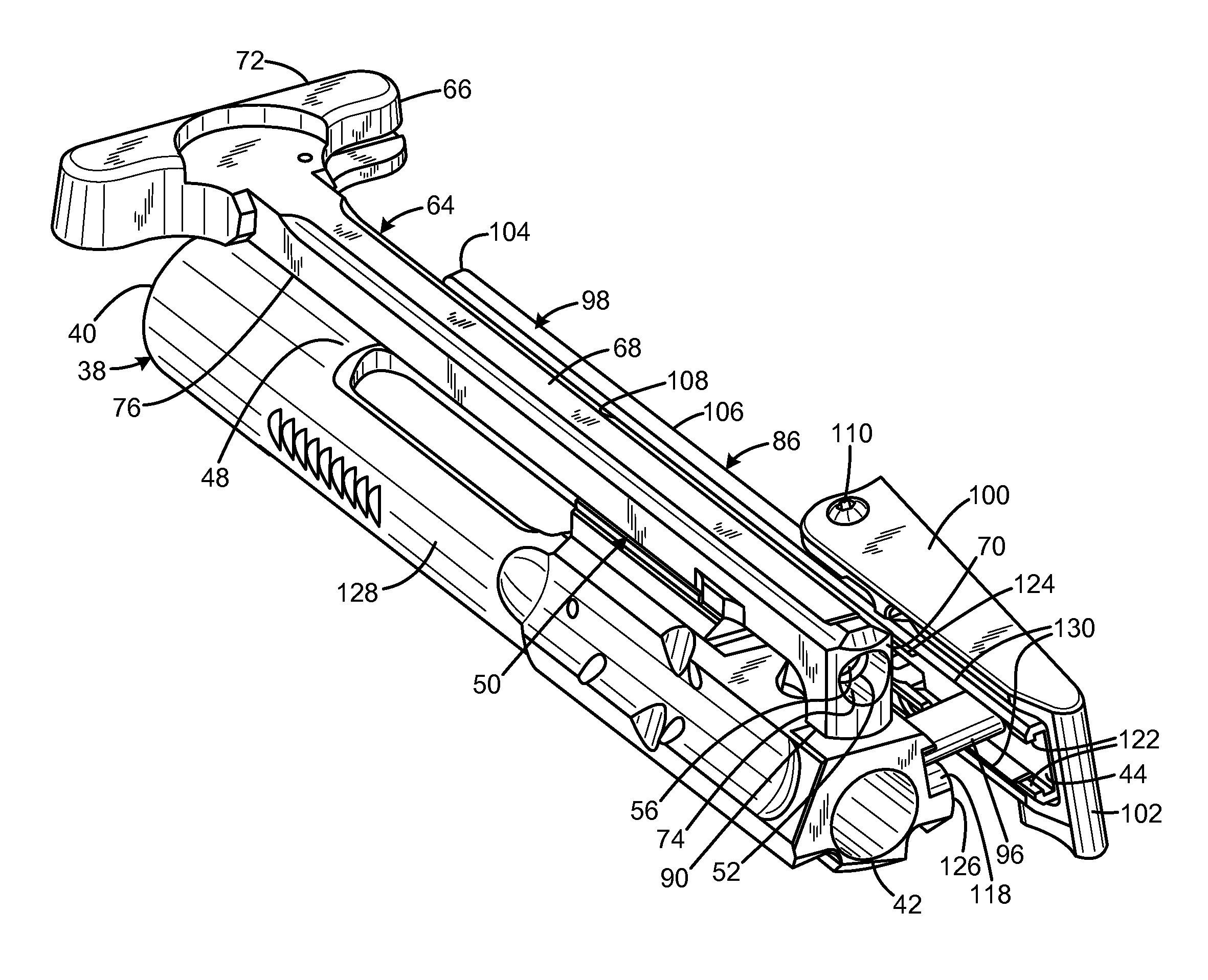
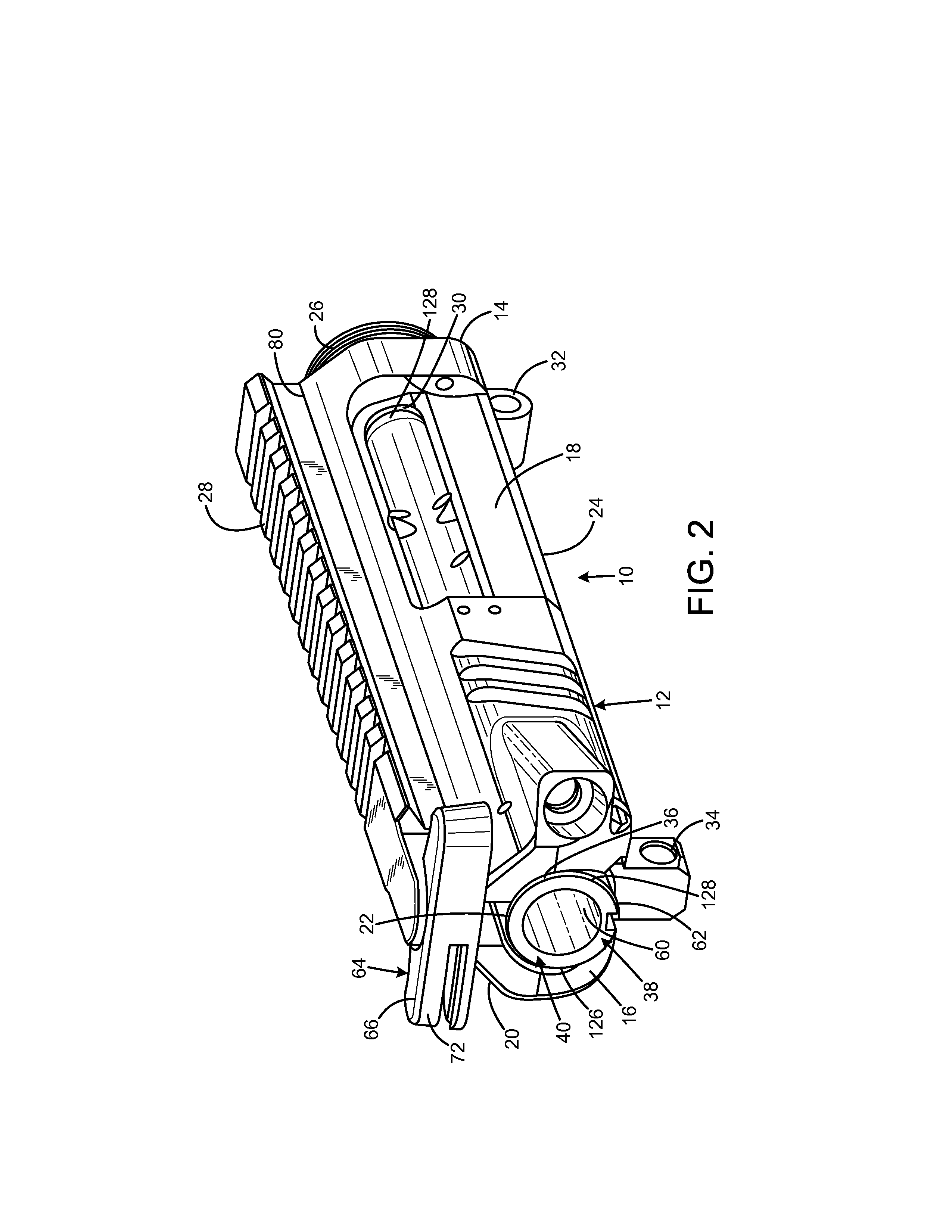
[0035]FIGS. 2-4C illustrate the improved upper receiver assembly 10 of the present invention. More particularly, the upper receiver assembly has been removed from the firearm 20...


PUM


Abstract

A firearm with dual charging handles is a rifle having a frame defining an elongated bolt passage, a bolt assembly received within the bolt passage and operable to reciprocate between a forward battery position and a rearward retracted position, a first elongated charging handle having a rear end extending rearward of the rear aperture of the frame, an intermediate portion received in the aperture, and a forward end within the bolt passage and adapted to operably contact the bolt, the frame defining an elongated slot parallel to the bolt passage and communicating therewith, and a second charging handle having a handle portion external of the bolt passage, an intermediate portion extending through the slot, and a contact element adapted to operably contact the bolt. The first charging handle may have a T shape. The second charging handle may include a dust cover overlaying the slot.

Description

FIELD OF THE INVENTION[0001]The present invention relates to firearms, and more particularly to a firearm having both top-mounted and side-mounted charging handles.BACKGROUND OF THE INVENTION[0002]The charging handle is a device on a firearm which, when operated, results in the hammer or striker being cocked or moved to the ready position. It allows the operator to pull the bolt to the rear, facilitating any number of the following:[0003]Ejecting a spent shell casing or unfired cartridge from the chamber.[0004]Loading a round from the magazine or by hand through the chamber.[0005]Clearing a stoppage such as a jam, double feed, stovepipe, or misfire.[0006]Verifying the weapon's chamber is clear of any rounds or other obstructions.[0007]Moving the bolt into battery, acting as a forward assist but not necessarily.[0008]Releasing a bolt locked to the rear, such as would be the case after firing the last round on a firearm equipped with a last-round-hold-open feature.[0009]These devices ...

Claims


Application Information

Patent Timeline
IPC IPC(8): F41A3/12F41C7/00
CPCF41A3/18F41A3/72
Inventor GANGL, JOHN P.CAMMACK, DAVID J.
Owner GANGL JOHN P
Why Eureka
Try Eureka