Beverage container

a beverage container and container body technology, applied in the field of beverage containers, can solve the problems of beverage container variation, incomplete installation, and the failure of the plug body to be attached to the beverage container, and achieve the effects of convenient formation, simple structure and favorable washability

Active Publication Date: 2013-07-11
THERMOS LLC
View PDF27 Cites 15 Cited by
  • Summary
  • Abstract
  • Description
  • Claims
  • Application Information

AI Technical Summary

Benefits of technology

[0024]According to the invention described in the first aspect, the spewing of a beverage from the beverage container can be restricted at the time of opening the lid, even when the pressure is being applied. The valve is not manually opened and closed, but is configured to be able to react to a suction force occurring in the fluid passage. Therefore, only a relatively small number of additional parts are needed to solve a problem such as the spewing of a content fluid that occurs at the time of opening the drinking mouth. Further, since the valve member is detachable, it has a favorable washability.
[0025]According to the invention described in the second aspect, the positioning step section allows the cylindrical main body to be preci...

Problems solved by technology

Here, a plug body may fail to be attached to a beverage container if a beverage cylindrical member fails to appropriately come into contact with an inner bottom section of the corresponding beverage container.
Specifically, such failure occurs when the beverage cylindrical member to be installed in the beverage container is made of a hard material, accompanied by problems such as an incomplete installation and/or a variation in the size of the beverage container.
Further, the aforementioned failu...

Method used


Image

  • Beverage container
  • Beverage container
  • Beverage container

Examples


first embodiment

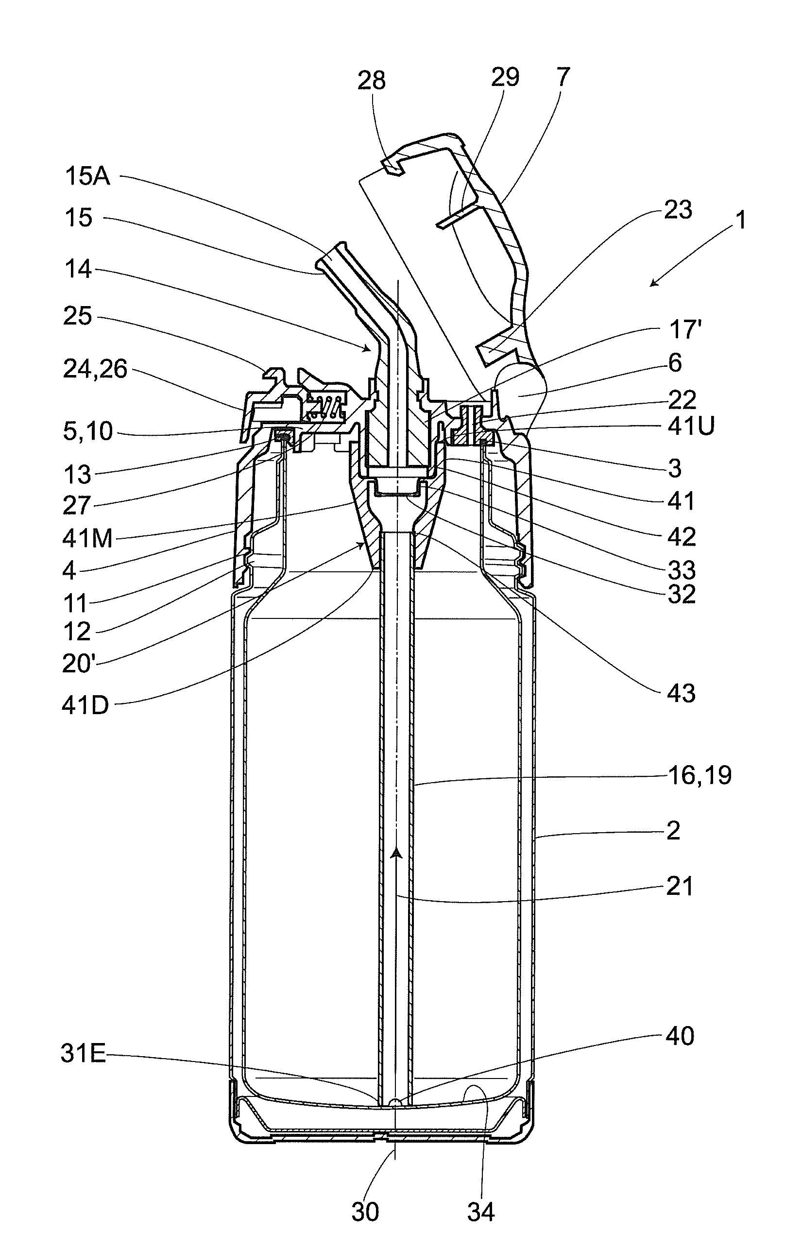
[0039]In FIG. 1 through FIG. 7, a numerical symbol “1” represents, as a whole, a portable beverage container of the present invention. The beverage container 1 has a sealed structure, and includes: a metallic container main body 2; and a plug body 4 that is made of a synthetic resin and joined to a container opening 3 of the container main body 2. An openable cup-shaped lid 7 is provided on the plug body 4 through a hinge member 6 attached to a one end side of a top section 5 of the plug body 4. Here, the lid 7 is capable of being held in a closed state through a locking mechanism 24 provided on an opposite side of the hinge member 6.

[0040]The plug body 4 includes a plug main body 10 of an inverted bottomed cylindrical shape. Particularly, the plug main body 10 is provided with the aforementioned top section 5 covering an upper opening section of the container main body 2. Further, a female screw portion 11 formed on an inner circumferential surface of the plug main body 10, is allo...

second embodiment

[0066]Other embodiments of the present invention are described hereunder. Here, elements identical to those of the first embodiment are marked with identical numerical symbols, and the descriptions thereof are thereby omitted.

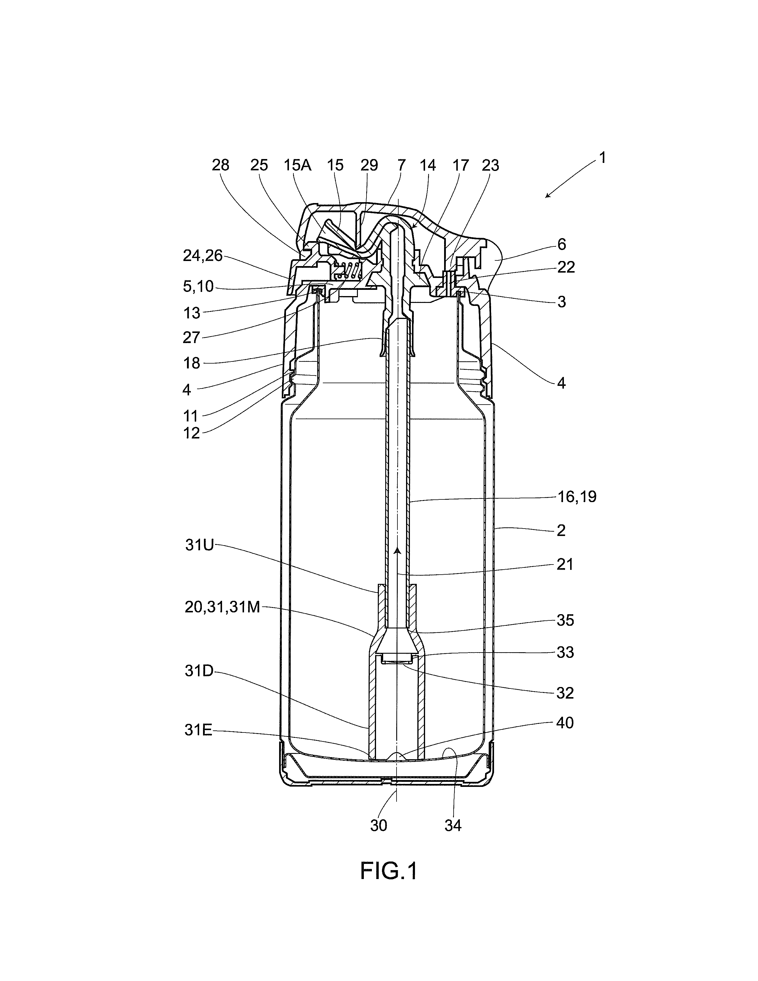
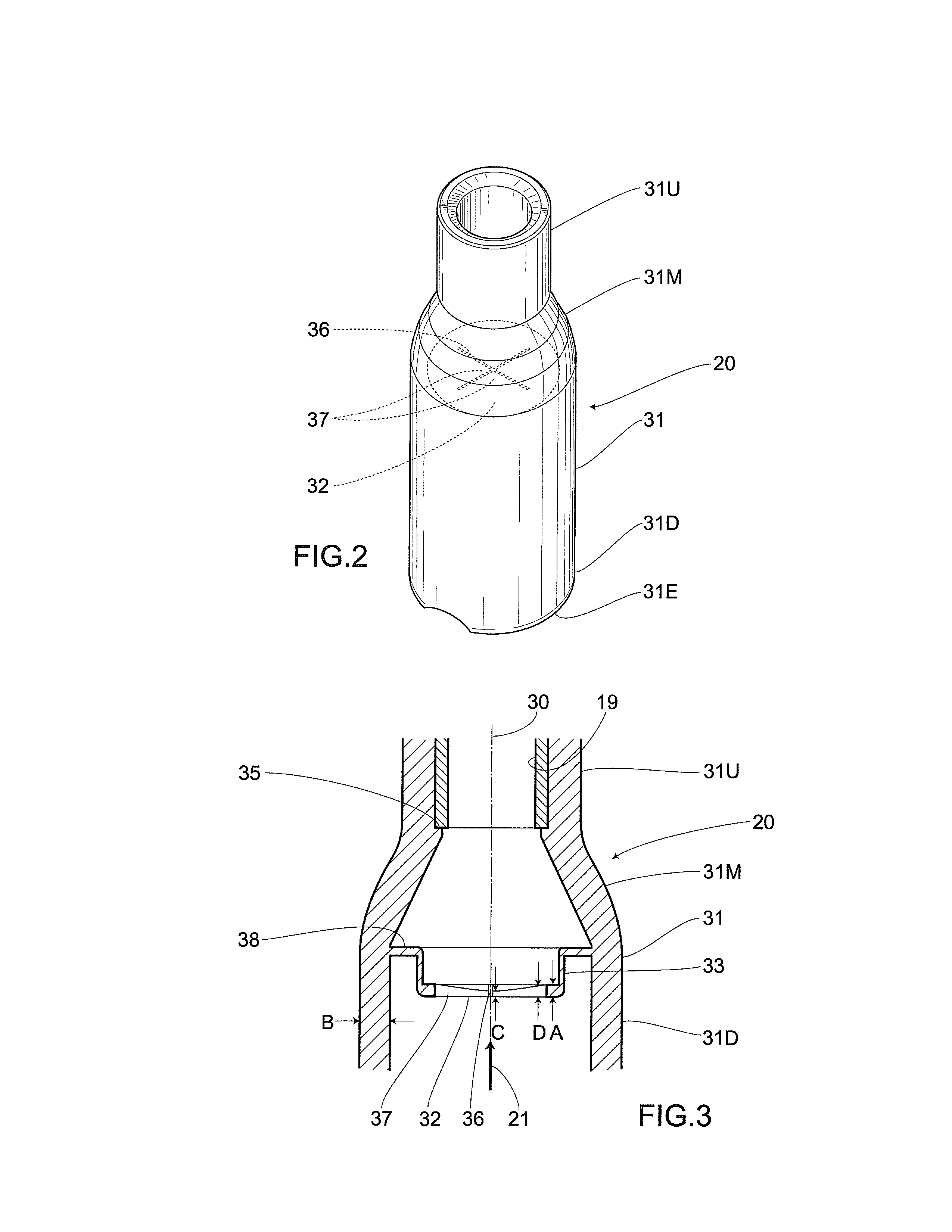
[0067]A second embodiment is shown in FIG. 7 through FIG. 9. A positioning section 17′ is provided on the base side of the drinking mouth portion 15, i.e., an under surface side of the plug body 4. The cylindrical main body 19 pointing downward is then joined to the positioning section 17′ through a valve unit 20′. In the present embodiment, a cylindrical portion 41 pointing downward is provided between the positioning section 17′ and a cylindrical portion 31′ of the valve unit 20′. Further, the cylindrical portion 41 is integrally provided on the plug body 4.

[0068]With regard to an outer circumference of the cylindrical portion 31′, while an upper section 31U′ has a larger diameter, a lower end 31D′ has a smaller diameter. Particularly, the cylindrical portion...


PUM


Abstract

A drinking mouth portion pointing upward is provided on a plug body of a container main body having a sealed structure. A down-pointing beverage cylindrical member is built into the container main body and has a front edge side thereof communicated with the drinking mouth portion. Provided inside a fluid passage of the beverage cylindrical member is a valve movable in accordance with a pressure difference therein. The valve is not manually opened and closed, but reacts to a suction force in the fluid passage. An up-pointing cut-out section is provided on a lower edge of the beverage cylindrical member, thus allowing one to drink up a content fluid remaining in an inner bottom section. Therefore, a relatively small number of additional parts are needed to address the spewing of a content fluid and the occurrence of a residual liquid at the time of opening the drinking mouth portion.

Description

BACKGROUND OF THE INVENTION[0001]1. Field of the Invention[0002]The present invention relates to a beverage container including a beverage cylindrical member.[0003]2. Description of Related Art[0004]Conventionally, there has been known a beverage container including: an up-pointing drinking mouth portion that is provided on a plug body of a container main body having a sealed structure; a lid that covers the drinking mouth portion and is pivotally provided on the plug body; and a down-pointing beverage cylindrical member that has a front edge thereof communicated with the drinking mouth portion and is built into the container main body. The aforementioned beverage container has a problem of, for example, causing a content fluid to spew out of the drinking mouth portion through the beverage cylindrical member when an inner pressure of the container main body is higher than the atmospheric pressure at the time of opening the lid so as to start to drink the content fluid.[0005]In order...

Claims


Application Information

Patent Timeline
IPC IPC(8): B65D51/16
CPCA47G19/2266B65D51/1644B65D47/2031B65D47/06B65D47/20B65D47/32
Inventor FUJITA, MAMORUMATSUYAMA, SHIN
Owner THERMOS LLC
Why Eureka
Try Eureka