Aircraft with fixed and tilting thrusters

a thruster and fixed technology, applied in the field of aircraft, can solve the problems of severe flying hazards, inability to provide full controllability to the flying body, and the platform of the helicopter is natively unstabl

Inactive Publication Date: 2013-07-11
SHEFER MORDECHAI
View PDF3 Cites 68 Cited by
  • Summary
  • Abstract
  • Description
  • Claims
  • Application Information

AI Technical Summary

Benefits of technology

[0023]The aircraft also includes one or more aerodynamic foils, such as wings that are substantially parallel to a second plane defined by the pitch and roll axes, and / or is such as a rudder that is substantially parallel to the roll axis and that preferably is parallel to the first plane, that are fixedly connected to the fuselage. An “aerodynamic foil” is defined herein as a relatively thin (in one of its three dimensions) solid object that protrudes from the fuselage into the airflow around the aircraft to provide lift and / or stability. This / these aerodynamic foil(s) lack movable flight control surfaces such as elevons or rudders.

Problems solved by technology

Two rotors cannot possibly provide full controllability to a flying body, therefore the helicopter is a natively unstable platform.
This in turn presents severe flying hazards as well as severe maneuverability limits.
The disadvantage of the quadrotor is its severe speed and maneuverability limits which are induced by the fixed rotors attitudes in the body frame.
Such a body-tilting is limited to small angles and it is also a time-consuming process that severely suppresses the vehicle's agility and response.
Hence, the DTR configuration is natively unstable in hovering.
This in turn induces flying hazards and poor maneuverability and response of the vehicle.
Too many degrees of freedom in the control resources which in turn require an exceedingly complex and expensive locomotion and attitude control system.

Method used


Image

  • Aircraft with fixed and tilting thrusters
  • Aircraft with fixed and tilting thrusters
  • Aircraft with fixed and tilting thrusters

Examples


Embodiment Construction

[0031]The principles and operation of a FHV according to the present invention may be better understood with reference to the drawings and the accompanying description.

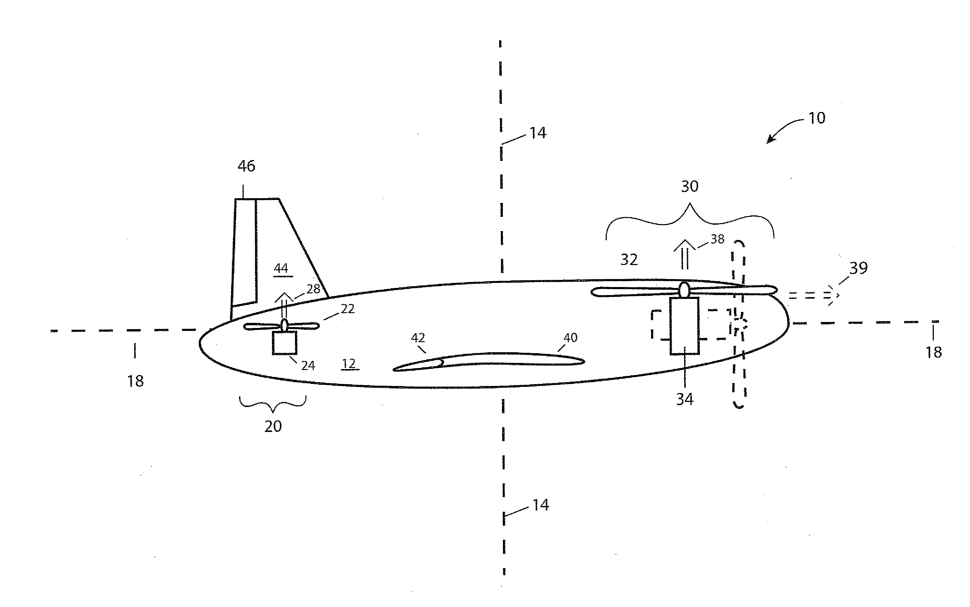
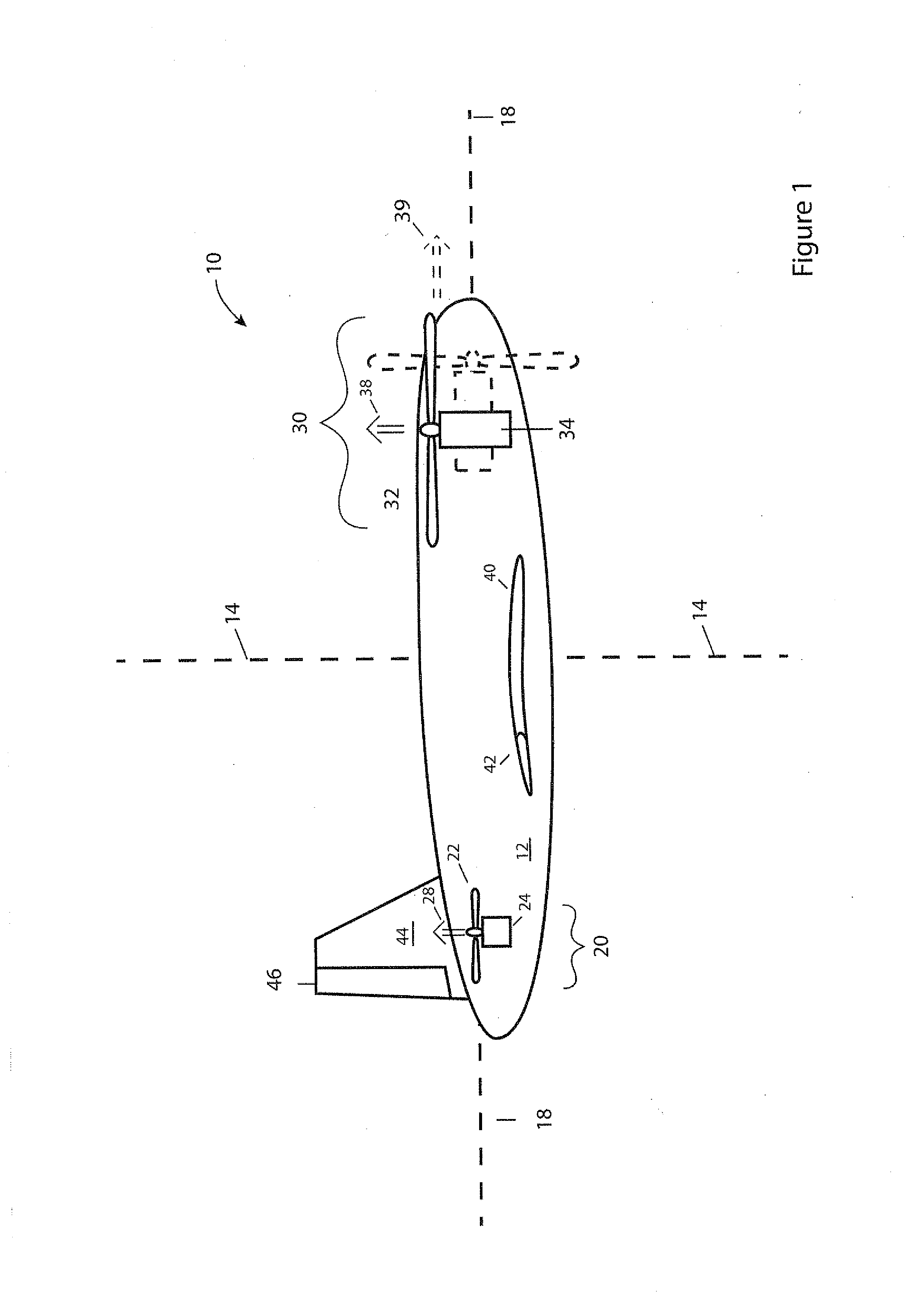
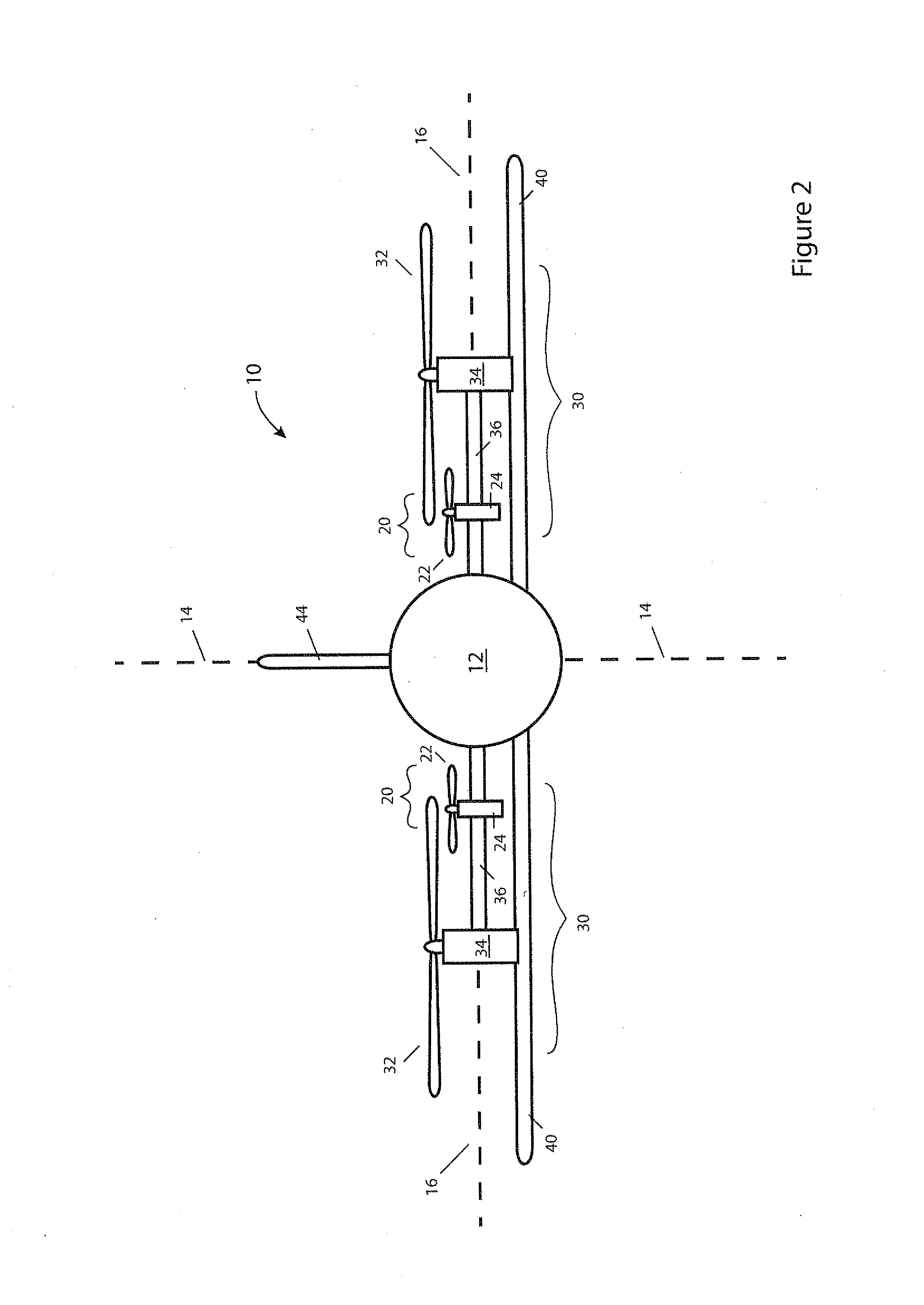
[0032]Referring now to the drawings, FIGS. 1-3 are, respectively, side, front and bottom views of an aircraft 10 of the present invention.

[0033]The core of aircraft 10 is a rigid fuselage 12. The turning maneuvers of aircraft 10 are defined in terms of three mutually perpendicular body-centered axes of fuselage 12: a yaw axis 14, a pitch axis 16 and a roll axis 18.

[0034]Extending laterally from both sides of fuselage 12, towards the front of fuselage 12, are two shafts 36 that support respective locomotion and hover thrusters 30. Each locomotion and hover thruster 30 includes a propeller 32 and a motor 34 for spinning propeller 32. Shafts 36 are coupled to motors (not shown) within fuselage 12 that turn shafts 36 to tilt locomotion and hover thrusters 30 parallel to the plane defined by axes 14 and 18, similar to how ...


PUM


Abstract

An aircraft including a fuselage with a yaw axis, a pitch axis and a roll axis, two attitude control thrusters, fixedly connected to the fuselage to provide thrust parallel to the yaw axis, two locomotion and hover thrusters. The aircraft further includes for the locomotion and hover thruster, a mechanism for tilting the locomotion and hover thruster about a tilt axis parallel to the pitch axis to select a direction, parallel to a first plane defined by the yaw and roll axes, in which the locomotion and hover thruster provides thrust.

Description

FIELD AND BACKGROUND OF THE INVENTION[0001]The present invention relates to aircraft and, more particularly, to an aircraft that can take off and land vertically, hover, fly rapidly in any desired direction, and maneuver in tight spaces.[0002]Various attempts have been made to achieve the combination of hovering and flying capabilities in one flying-and-hovering vehicle (FHV). The most familiar FHV is the helicopter. A typical helicopter is equipped with one large rotor, that rotates only in a horizontal plane, for locomotion, and one aft rotor, that rotates only in a vertical plane, for stabilization. The helicopter has two main disadvantages, which are,[0003]i. The large rotor axis is fixed in the body frame, therefore its flying velocity typically is limited to about 150 Km / hr.[0004]ii. Two rotors cannot possibly provide full controllability to a flying body, therefore the helicopter is a natively unstable platform. This in turn presents severe flying hazards as well as severe ma...

Claims


Application Information

Patent Timeline
Patent Type & Authority Applications(United States)
IPC IPC(8): B64C39/00
CPCB64C39/00B64C39/024B64C29/0033B64C15/14B64C27/26
Inventor SHEFER, MORDECHAI
Owner SHEFER MORDECHAI
Why Eureka
Try Eureka