Output control system, output control method, and output control apparatus

a control system and control method technology, applied in the direction of digital output to print units, instruments, computing, etc., can solve the problems of difficult to flexibly change the print mode depending and difficult to flexibly change the print mod

Inactive Publication Date: 2013-07-11
RICOH KK
View PDF2 Cites 205 Cited by
  • Summary
  • Abstract
  • Description
  • Claims
  • Application Information

AI Technical Summary

Benefits of technology

[0009]It is an object of the present invention to at least

Problems solved by technology

Therefore, it is difficult to flexibly change the print mode depending on operation conditions.
Th

Method used


Image

  • Output control system, output control method, and output control apparatus
  • Output control system, output control method, and output control apparatus
  • Output control system, output control method, and output control apparatus

Examples


first embodiment

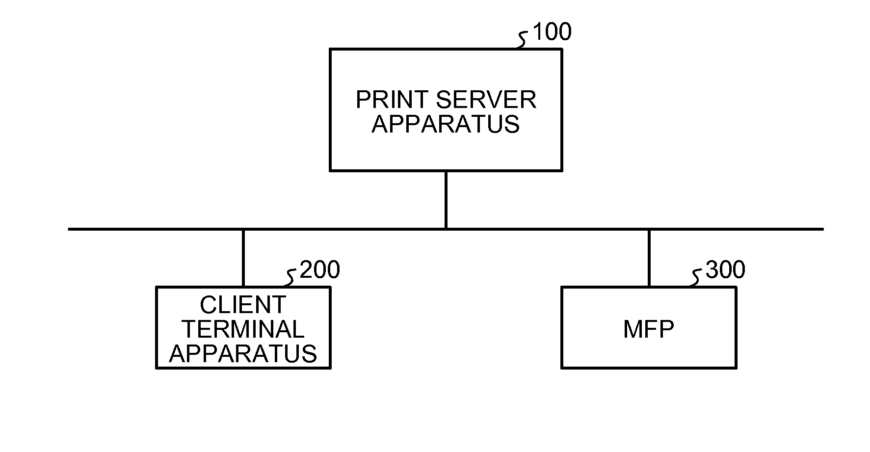
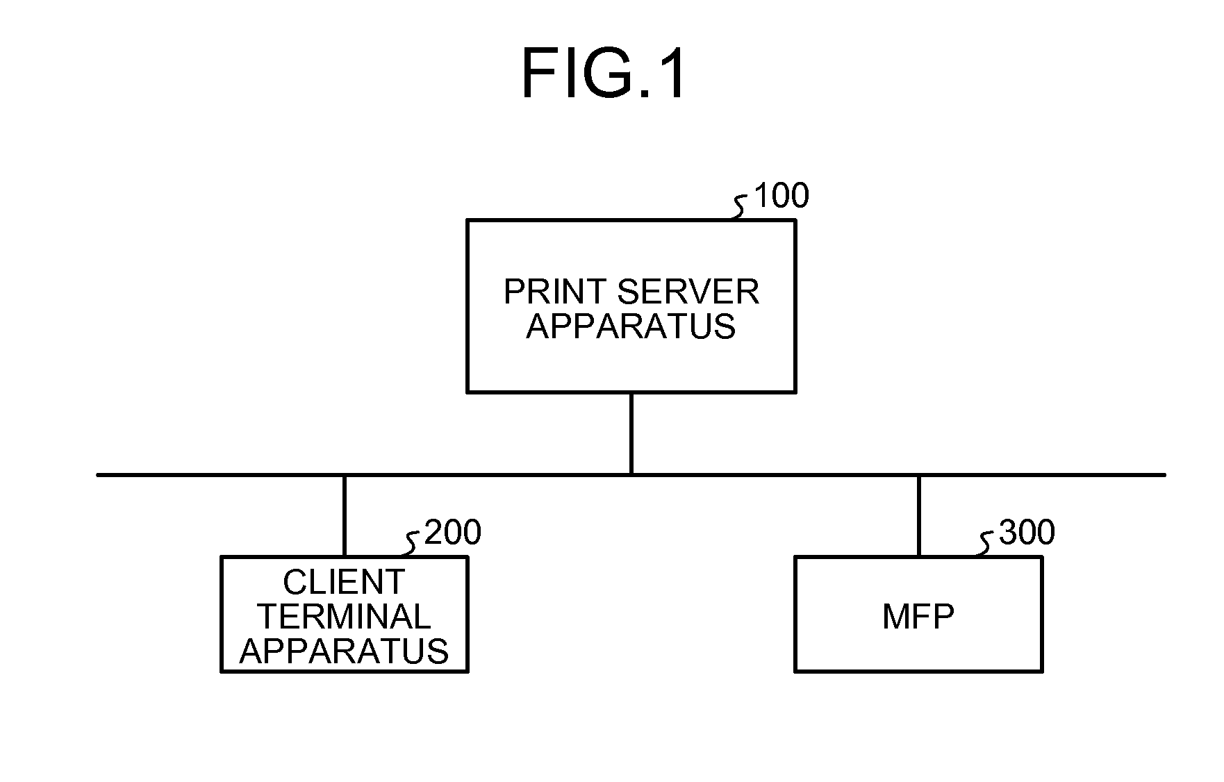
[0032]FIG. 1 is a diagram illustrating the overall structure of an output control system according to a first embodiment. As illustrated in FIG. 1, the output control system according to this embodiment includes a print server apparatus 100, a client terminal apparatus 200, and a multifunction peripheral (MFP) 300 which are connected so as to communicate with each other through a network such as a local area network (LAN). In FIG. 1, one MFP 300 is illustrated. However, it is assumed that a plurality of MFPs are connected to the LAN in a printing environment according to this embodiment. In addition, a plurality of client terminal apparatuses 200 may be connected.

[0033]The print server apparatus 100 is an apparatus in which print server applications operate, manages a print job including print data (output target data) and conditions for printing (outputting) the print data, and transmits the print job including the print data to a designate MFP such that the print data is printed. ...

second embodiment

[0068]In the output control system according to the first embodiment, when a print job is received from the client terminal apparatus and another user logs in the designated MFP, the print server apparatus performs “hold print” in which the print job is stored in the job storage unit 107 and is then printed. In contrast, in an output control system according to this embodiment, when another user logs in the designated MFP, the print server apparatus searches for MFPs which are not in the login state and allows the user to select an MFP which will perform printing instead of the designated MFP from the searched MFPs.

[0069]Since the overall structure of the output control system according to this embodiment is the same as that of the output control system according to the first embodiment, the description thereof will not be repeated (see FIG. 1).

[0070]Next, the functional structures of a print server apparatus 400, a client terminal apparatus 500, and an MFP 300 forming the output co...

third embodiment

[0087]In the output control system according to the first embodiment, when the logout input is received from the user, the MFP transmits its use state to the print server apparatus. In contrast, in an output control system according to this embodiment, when the MFP receives the logout input from the user and has completed the printing of the print data, it transmits its use state to the print server apparatus.

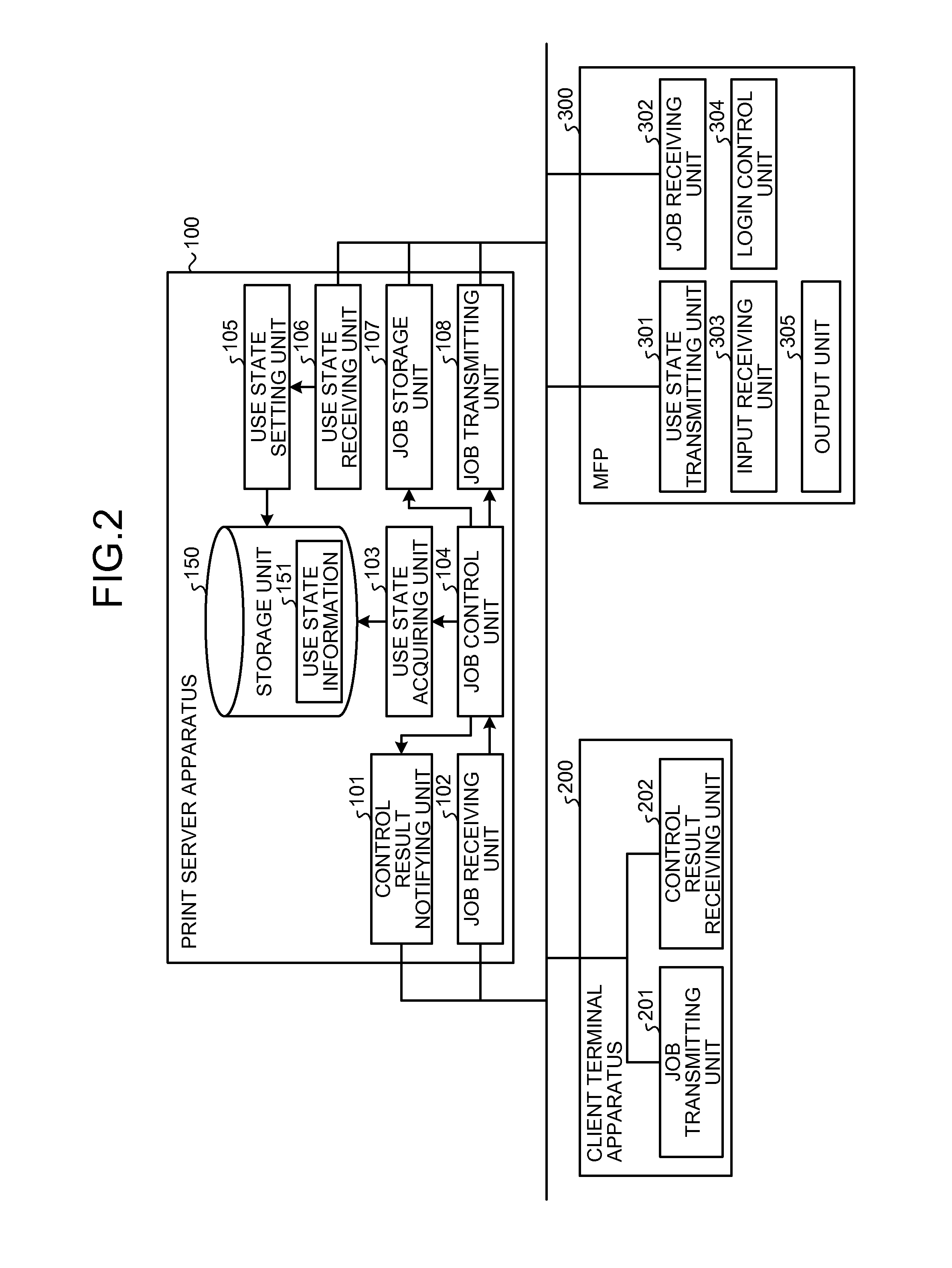
[0088]In this embodiment, the output control system has the same overall structure as that in the first embodiment and a print server apparatus 100 and a client terminal apparatus 200 have the same structure and function as those in the first embodiment. Therefore, the description thereof will not be repeated (see FIGS. 1 and 2). In addition, in this embodiment, an MFP 300 has the same structure as that in the first embodiment except that a use state transmitting unit 301 has the following functions.

[0089]When the use state of the MFP 300 is changed, the use state transmitting ...


PUM


Abstract

An output control apparatus includes a state information storage unit configured to store therein state information in which apparatus identification information about an output apparatus and a use state of the output apparatus are associated; a use state management unit configured to store the state information for the use state received from the output apparatus in the state information storage unit; a designation of the output apparatus, and a request to output the target data to the designated output apparatus; an output control unit configured to determine whether to store the target data in a data storage unit or transmit the target data to the designated output apparatus based on the use state of the designated output apparatus; and a data transmitting unit configured to transmit the target data and the request to the designated output apparatus when the target data is to be transmitted to the designated output apparatus.

Description

CROSS-REFERENCE TO RELATED APPLICATION[0001]The present application claims priority to and incorporates by reference the entire contents of Japanese Patent Application No. 2012-001588 filed in Japan on Jan. 6, 2012.BACKGROUND OF THE INVENTION[0002]1. Field of the Invention[0003]The present invention relates to an output control system, an output control method, and an output control apparatus.[0004]2. Description of the Related Art[0005]There is a demand for a technique which is capable of improving security while considering convenience in a network printing environment in which a print job is transmitted from a client terminal apparatus, such as a personal computer (PC), to an image forming apparatus, such as a multifunction peripheral (MFP), through a network and is then printed. As a method of implementing the technique which is capable of improving security while considering convenience, for example, in general, a method has been known which performs switching between hold prin...

Claims


Application Information

Patent Timeline
IPC IPC(8): G06F3/12
CPCG06F3/1296G06F3/1222G06F3/1288G06F3/1267G06F3/1238
Inventor SASAKI, KOJI
Owner RICOH KK
Why Eureka
Try Eureka