System, Method, and Apparatus for Infusing Fluid

Active Publication Date: 2013-07-11
DEKA PROD LLP
View PDF2 Cites 307 Cited by
  • Summary
  • Abstract
  • Description
  • Claims
  • Application Information

AI Technical Summary

Benefits of technology

[0043]In some embodiments, the pump also includes a balancer cam, a balancer-cam follower, and a balancer spring configured to apply a force against the balancer-cam follower and thereby ap

Problems solved by technology

Despite the existence of systems intended to facilitate the care process, such as those incorporating electronic medical records (“EMR”) and computerized provider order entry (“CPOE”)

Method used


Image

  • System, Method, and Apparatus for Infusing Fluid
  • System, Method, and Apparatus for Infusing Fluid
  • System, Method, and Apparatus for Infusing Fluid

Examples


Embodiment Construction

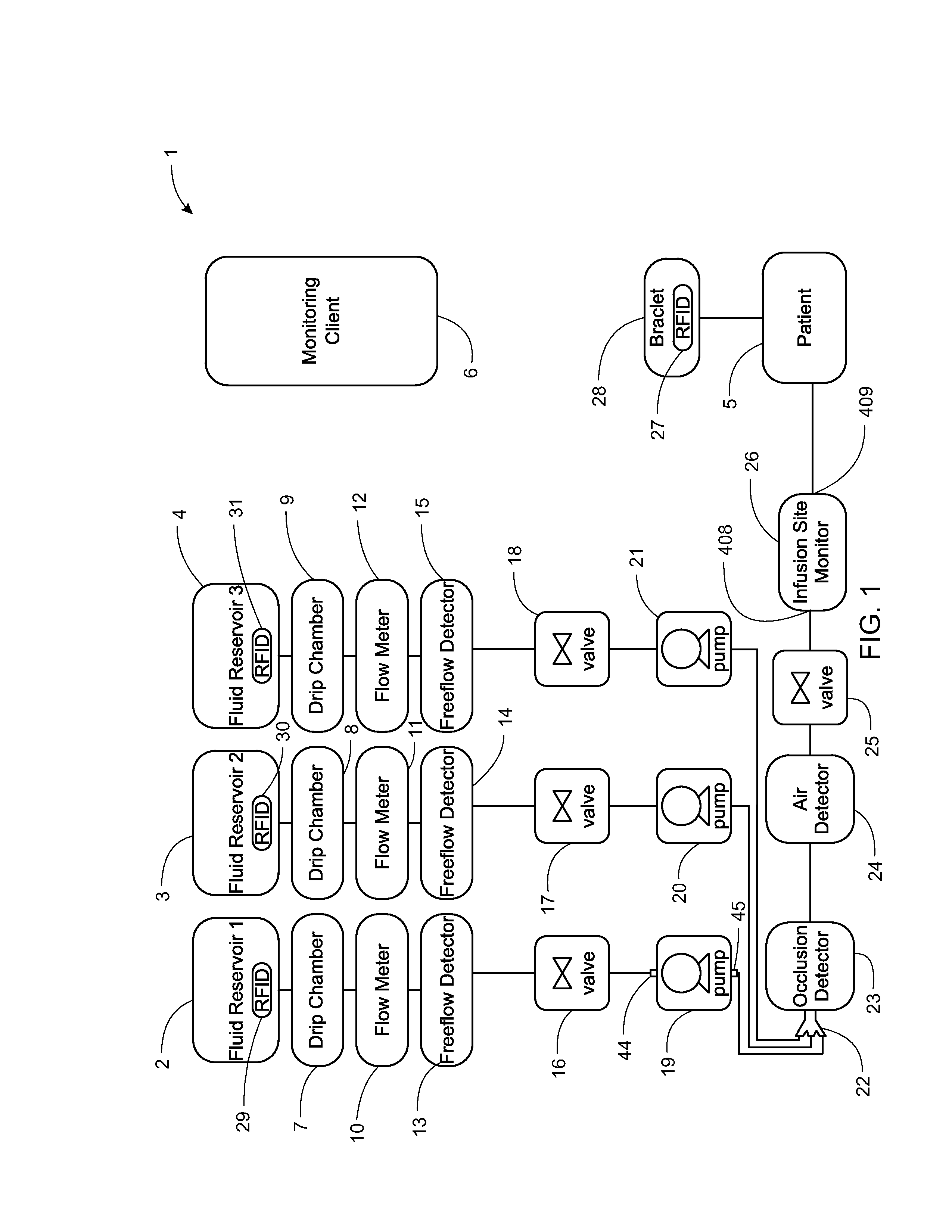
[0298]FIG. 1 shows a block diagram of a system 1 for infusing fluid. System 1 includes fluid reservoirs 2, 3, and 4 for infusing the fluid contained therein into a patient 5. The fluid reservoirs 2, 3, and 4 are gravity fed into drip chambers 7, 8, and 9, respectively. The drip chambers 7, 8, and 8 are respectively fed into flow meters 10, 11, and 12. From the flow meters 10, 11, and 12, the fluid is fed into free-flow detectors 13, 14, and 15, respectively.

[0299]System 1 also includes valves 16, 17, and 18 from a respective free-flow detector of the free-flow detectors 13, 14, and 15. Pumps 19, 20, and 21 receive fluid from valves 16, 17, and 18, and combine the fluid using a connector 22. The valves 16, 17, and 18 may be in wireless or wired communication with a respective pump 19, 20, and 21 to control the flow rate and / or discharge profile. For example, the pump 19 may communicate wirelessly with the valve 16 to adjust the opening and closing of the valve 16 to achieve a target ...


PUM


Abstract

A peristaltic pump, and related system method are provided. The peristaltic pump includes a cam shaft, first and second pinch-valve cams, first and second pinch-valve cam followers, a plunger cam, a plunger-cam follower, a tube receiver, and a spring-biased plunger. The first and second pinch-valve cams are coupled to the cam shaft. The first and second pinch-valve cam followers each engage the first and second pinch-valve cams, respectively. The plunger cam is coupled to the cam shaft. The plunger-cam follower engages the plunger cam. The tube receiver is configured to receive a tube. The spring-biased plunger is coupled to the plunger-cam follower such that the expansion of the plunger cam along a radial angle intersecting the plunger-cam follower as the cam shaft rotates pushes the plunger cam follower towards the plunger and thereby disengages the spring-biased plunger from the tube. A spring coupled to the spring-biased plunger biases the spring-biased plunger to apply the crushing force to the tube.

Description

CROSS REFERENCE TO RELATED APPLICATIONS[0001]The present application is a Non-Provisional application which claims priority to and the benefit of the following:[0002]U.S. Provisional Patent Application Ser. No. 61 / 578,649, filed Dec. 21, 2011 and entitled System, Method, and Apparatus for Infusing Fluid (Attorney Docket No. J02);[0003]U.S. Provisional Patent Application Ser. No. 61 / 578,658, filed Dec. 21, 2011 and entitled System, Method, and Apparatus for Estimating Liquid Delivery (Attorney Docket No. J04);[0004]U.S. Provisional Patent Application Ser. No. 61 / 578,674, filed Dec. 21, 2011 and entitled System, Method, and Apparatus for Dispensing Oral Medications (Attorney Docket No. J05);[0005]U.S. Provisional Patent Application Ser. No. 61 / 679,117, filed Aug. 3, 2012 and entitled System, Method, and Apparatus for Monitoring, Regulating, or Controlling Fluid Flow (Attorney Docket No. J30); and[0006]U.S. Provisional Patent Application Ser. No. 61 / 651,322, filed May 24, 2012 and enti...

Claims


Application Information

Patent Timeline
IPC IPC(8): F04B43/12G01F1/66
CPCG06F19/3418G06F19/3468G06Q50/22A61M2005/16863G01F1/666A61M5/14228A61M5/16831F04B43/12G16H20/17G16H40/67F04B43/082F04B43/08F04B43/09F04B49/065F04B49/00F04B2205/09F04B43/1261G16H50/00G16H40/63
Inventor KAMEN, DEANKERWIN, JOHN M.MURPHY, COLIN H.GRAY, LARRY B.LANGENFELD, CHRISTOPHER C.SLATE, MICHAEL J.PLACE, MICHAEL S.LANIER, JR., GREGORY R.
Owner DEKA PROD LLP
Why Eureka
Try Eureka