Catalyst abnormality diagnosis apparatus

a technology of abnormal diagnosis and catalyst, which is applied in the direction of electrical control, exhaust treatment electric control, instruments, etc., can solve the problems of higher error rate, measurement errors, and reduced conversion efficiency of degraded catalysts, and achieve the effect of reducing the error rate of the output measurement immediately before the inversion of the post-catalyst sensor outpu

Active Publication Date: 2013-07-18
TOYOTA JIDOSHA KK
View PDF5 Cites 6 Cited by
  • Summary
  • Abstract
  • Description
  • Claims
  • Application Information

AI Technical Summary

Benefits of technology

[0013]in that when an output from the post-catalyst sensor reaches a predetermined threshold, the active air-fuel ratio control means simultaneously switches between the lean control and the rich control, and the measurement means ends measuring

Problems solved by technology

On the other hand, a degraded catalyst has a reduced conversion efficiency.
However, when the amount of oxygen is measured, the amount of oxygen that is actually not absorbed or released is also measured, disadvantageously resulting in measurement errors.
In particular, according to the conventional Cmax method, an error rate measured immedi

Method used


Image

  • Catalyst abnormality diagnosis apparatus
  • Catalyst abnormality diagnosis apparatus
  • Catalyst abnormality diagnosis apparatus

Examples


Embodiment Construction

[0072]Preferred embodiments of the present invention will be described below with reference to the accompanying drawings.

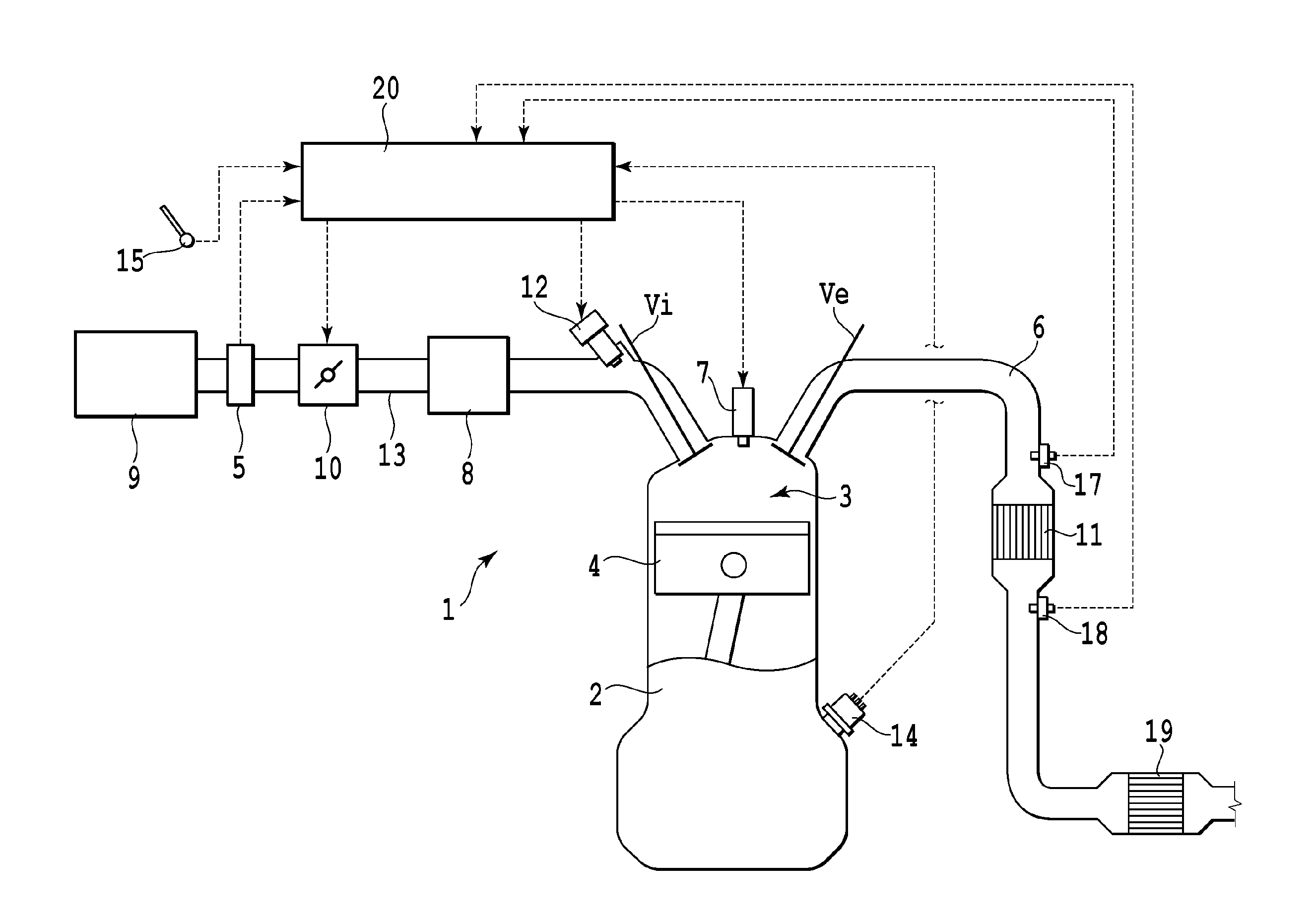
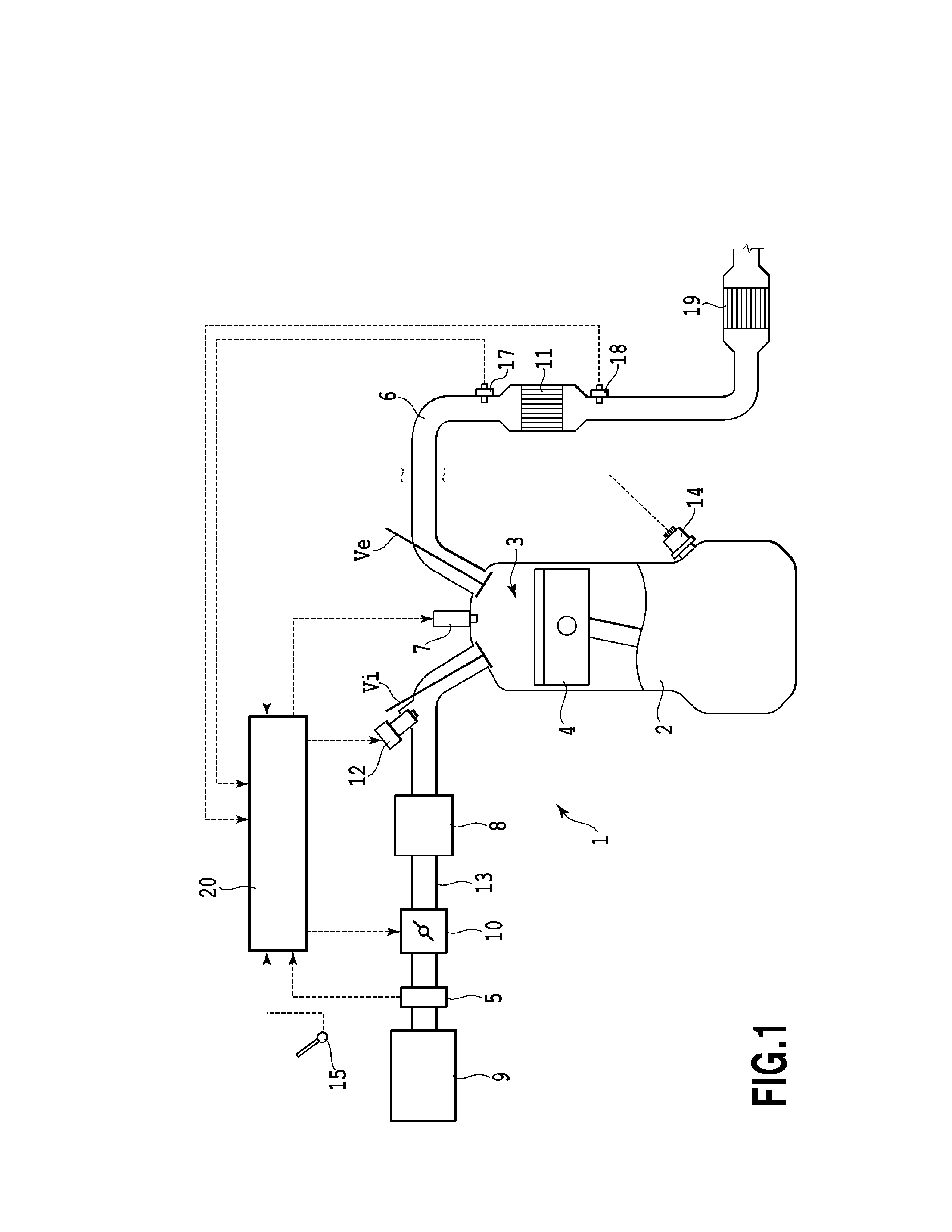
[0073]FIG. 1 is a schematic diagram showing a configuration according to the present embodiment. As shown in FIG. 1, an engine 1 that is an internal combustion engine combusts a mixture of fuel and air inside a combustion chamber 3 formed in a cylinder block 2 and reciprocates a piston 4 inside the combustion chamber 3 to generate power. The engine 1 according to the present embodiment is a multi-cylinder engine (only one cylinder is shown) and is a spark ignition internal combustion engine and more specifically a gasoline engine.

[0074]A cylinder head in the engine 1 includes intake valves Vi and exhaust valves Ve arranged therein so that each intake valve Vi and each exhaust value Ve correspond to one of the cylinders; the intake valve Vi opens and closes an intake port, and the exhaust valve Ve opens and closes an exhaust port. Each intake valve Vi and each exha...


PUM


Abstract

Active air-fuel ratio control is performed to alternately control an air-fuel ratio in an area located upstream of a catalyst between a lean side and a rich side. The amount of oxygen absorbed and released by the catalyst during lean control and rich control of the air-fuel ratio is measured. When an output from the post-catalyst sensor reaches a predetermined threshold, switching is carried out between the lean control and the rich control, and the measurement of the amount of oxygen is ended. The threshold is set to be reached before the output from the post-catalyst sensor reaches a predetermined reference value. Whether the catalyst is normal or abnormal is determined based on the amount of oxygen measured until the output from the post-catalyst sensor reaches the threshold and behavior of the output from the post-catalyst sensor observed after the output from the post-catalyst sensor reaches the threshold.

Description

TECHNICAL FIELD[0001]The present invention relates to abnormality diagnosis for a catalyst, and in particular, to an apparatus that diagnoses abnormality of the catalyst arranged in an exhaust passage in an internal combustion engine.BACKGROUND ART[0002]For example, automobile internal combustion engines include a catalyst installed in an exhaust system to purify exhaust gas. Some such catalysts have an O2 storage capability. When the air-fuel ratio of exhaust gas flowing into the catalyst is higher than a theoretical air-fuel ratio (stoichiometry), that is, the air-fuel ratio is indicative of a lean state, a catalyst with the O2 storage capability absorbs excess oxygen present in the exhaust gas. When the air-fuel ratio of the exhaust gas is lower than the stoichiometry, that is, the air-fuel ratio is indicative of a rich state, the catalyst releases the absorbed oxygen. For example, a gasoline engine controls the air-fuel ratio so as to set the air-fuel ratio of the exhaust gas fl...

Claims


Application Information

Patent Timeline
IPC IPC(8): F01N11/00
CPCF01N3/101F01N2550/02F01N2560/025F01N2900/0412F01N2900/0416F01N2900/0422F01N2900/1402F01N2900/1624F02D41/1441F02D41/1475Y02T10/47F02D41/0295F02D41/1456F02D2200/0814Y02T10/22F01N11/007Y02T10/12Y02T10/40
Inventor KITAURA, KOICHI
Owner TOYOTA JIDOSHA KK
Why Eureka
Try Eureka