Vehicle speed limiter

A vehicle speed limit and vehicle speed technology, which is applied in the field of vehicle speed limit devices, can solve the problems of the temperature rise of the exhaust purification device, shorten the life of the exhaust purification device, etc., and achieve the effect of reducing the cost

Inactive Publication Date: 2003-07-23
HONDA MOTOR CO LTD
View PDF1 Cites 3 Cited by
  • Summary
  • Abstract
  • Description
  • Claims
  • Application Information

AI Technical Summary

Problems solved by technology

Since the unburned gas is combusted in the exhaust purification device, the temperature of the ex

Method used


Image

  • Vehicle speed limiter
  • Vehicle speed limiter
  • Vehicle speed limiter

Examples


Embodiment Construction

[0026] Embodiments of the present invention will be described below with reference to the drawings. The accompanying drawings are shown in the direction of the reference numerals.

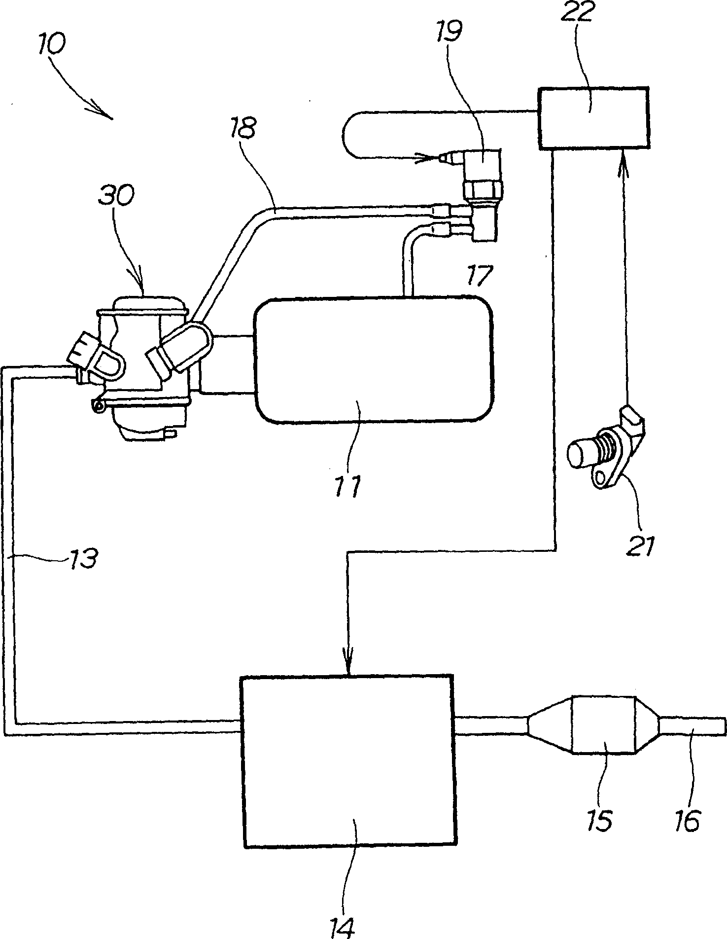
[0027] figure 1 It is a schematic diagram related to the vehicle speed limiting device of the present invention. The vehicle speed limiting device 10 is installed on the engine 14 to burn the mixed gas supplied by the air cleaner 11, the gasifier 30 and the air intake system 13 and pass through the engine 14 provided with a catalytic device 15. Exhaust system 16 is a device inside the internal combustion engine exhausted. The vehicle speed limiting device consists of auxiliary air passages 17, 18 branched from the air cleaner 11, and a solenoid valve 19 installed between these passages. The input is detected by the vehicle speed sensor 21. The control unit 22 is composed of the vehicle speed information and judges whether to implement the vehicle speed control and completes the ignition control an...


PUM


Abstract

The invention solves the problem that the quantity of unburnt gas is increased if a vehicle speed is limited by thinned-out ignition, CO, HC gas is increased and a load of the catalyst is increased, and the service life of the catalyst is considerably reduced. (a) shows control sections. A first vehicle speed threshold and a second vehicle speed threshold which is higher than the first one are set, and normal control is performed to the first vehicle speed threshold, lean control is performed between the first vehicle speed threshold and the second vehicle speed threshold, and the lean control and the ignition control (the thinned-out ignition) are performed above the second vehicle speed threshold. (b) shows the opening/closing operation of a solenoid valve, and (c) shows ignition control, and more specifically, the presence/absence of the thinned-out ignition. The vehicle speed is gradually reduced by the lean control in a first stage, and the vehicle speed is reliably reduced by the ignition control in a second stage. In the lean control, combustion is continued, the quantity of the unburnt gas is reduced, and an emission level can be increased.

Description

technical field [0001] The present invention relates to a vehicle speed limiting device for limiting the speed of a vehicle so as not to exceed a vehicle speed threshold. Background technique [0002] The output is reduced when the ignition is cut off (reducing the number of ignitions / insertion ki), thereby limiting the speed of the vehicle. [0003] As a speed limiting technology for vehicles, for example, it has been disclosed in JP-A-10-47143 "Fuel Limiting Device for Internal Combustion Engines", which is characterized in that figure 1 Among them, when the machine is abnormal, the control device 10 can throttle the electromagnetic switch valve 12 at short intervals to control the fuel in the carburetor 3 to prevent the engine from overspeeding, thereby protecting the catalyst from the influence of heating. [0004] The problem solved by the invention [0005] The CO / HC content in the exhausted unburned gas is increased. [0006] However, if the combustion amount is re...

Claims


Application Information

Patent Timeline
IPC IPC(8): F02M17/38F02D29/02F02D41/04F02D43/00F02D45/00F02M7/23F02M7/24F02M19/06F02P9/00
Inventor 松崎雅伸铃木祥介若山浩史片山淳
Owner HONDA MOTOR CO LTD
Why Eureka
Try Eureka