
Misfire detection apparatus and misfire detection method for an internal combustion engine

a technology of misfire detection and internal combustion engine, which is applied in the direction of internal combustion engine testing, machines/engines, electric control, etc., can solve the problems of significant fluctuation in rotation, engine misfire state cannot be correctly detected, and engine misfire state is incorrectly detected

Active Publication Date: 2016-01-26
MITSUBISHI ELECTRIC CORP
View PDF5 Cites 2 Cited by
  • Summary
  • Abstract
  • Description
  • Claims
  • Application Information

AI Technical Summary

Benefits of technology

The present invention provides a misfire detection apparatus and method for an internal combustion engine that is capable of correctly detecting a misfire state of an engine for a vehicle with a small number of cylinders and high rotational inertia without limiting control to O2 feedback control. The apparatus and method use the air / fuel ratio of the exhaust gas from a cylinder as a reference for detecting misfire. By enriching the air / fuel ratio of the exhaust gas from a misfiring cylinder and monitoring its level, misfire can be correctly identified. This system can also be used to detect misfire in a vehicle with a small number of cylinders, providing an effective solution for identifying this issue in a reliable and accurate way.

Problems solved by technology

However, the related arts have the following problems.
Sho 58-19532 is applied to a vehicle small in number of cylinders such as a V-twin engine and small in rotational inertia due to a small flywheel (such as a two-wheeled vehicle), fluctuation in rotation is significant, and the misfire state of the engine cannot be correctly detected.
In other words, fluctuation in rotation in a normal state without misfire is increased due to influence of a difference in combustion state generated between cylinders, and a determination error in misfire and a loss in detection of the misfire thus occur, resulting in incorrect detection of the misfire state of the engine.
In this case, the unburned gas exhausted in the misfire state and the burned gas exhausted in the normal state reach a detection area of the air / fuel ratio sensor in a mixed manner, and a difference in rich / lean cycle between the misfire state and the normal state may not be correctly detected.
Thus, the misfire state of the engine may not be correctly detected based on the rich / lean cycle of the detection signal from the air / fuel ratio sensor.
Moreover, in the related art described in Japanese Patent No. 5208289, when lengths from the plurality of cylinders of the engine to the collector of the exhaust pipes are different from each other, the burned gas and the unburned gas exhausted from the respective cylinders reach the detection area of the air / fuel ratio sensor at timings different from each other, and the difference in rich / lean cycle between the misfire state and the normal state may not be correctly detected.
Thus, there often occurs such a case that the value of the rich / lean cycle even after a normal combustion is not an intended value due to influence of fluctuation in the combustion states of the respective cylinders.
Therefore, the rich / lean cycle in the misfire state and that in the normal state cannot be distinguished from each other, and these states may not be correctly determined.

Method used


Image

  • Misfire detection apparatus and misfire detection method for an internal combustion engine
  • Misfire detection apparatus and misfire detection method for an internal combustion engine
  • Misfire detection apparatus and misfire detection method for an internal combustion engine

Examples


first embodiment

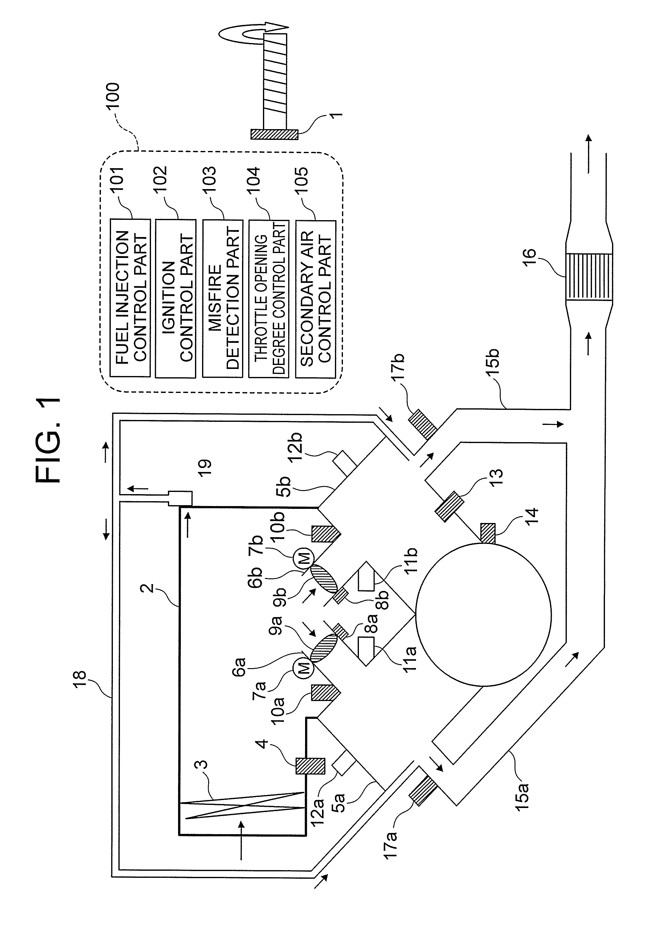
[0022]FIG. 1 is a configuration diagram illustrating an entire system including a misfire detection apparatus according to a first embodiment of the present invention. Note that, FIG. 1 illustrates a system configuration of a V-twin engine as an example.

[0023]In FIG. 1, an accelerator position sensor 1 detects a position of an accelerator opening degree. Moreover, an air filter 3 for purifying intake air to be supplied to the engine, and an intake air temperature sensor 4 for detecting a temperature of the intake air are installed on an air cleaner box 2 provided on an intake side of the engine.

[0024]A first cylinder 5a and a second cylinder 5b of the V-twin engine are provided on a downstream side of the air cleaner box 2. Moreover, a first intake pipe 6a and a second intake pipe 6b are respectively connected to the first cylinder 5a and the second cylinder 5b. The air in the air cleaner box 2 is supplied as intake air via the first intake pipe 6a to the first cylinder 5a, and via ...

second embodiment

[0091]According to the first embodiment, a description is given of such a case that, as the enrichment processing for the air / fuel ratio, the correction is carried out so as to increase the amount of the fuel supplied to the cylinder that is a misfire determination subject. In contrast, according to a second embodiment of the present invention, a description is given of such a case that, as the enrichment processing for the air / fuel ratio, the supply of the secondary air to the exhaust pipe connected to the cylinder that is a misfire determination subject is stopped. In the following section, a description is mainly given of a point different from the first embodiment, and a description of the same point is omitted.

[0092]FIG. 5 is a flowchart illustrating a series of operation steps of a misfire detection apparatus according to the second embodiment of the present invention. Note that, the flowchart in FIG. 5 is acquired by adding Step S406A to the flowchart in FIG. 4 in place of St...


PUM


Abstract

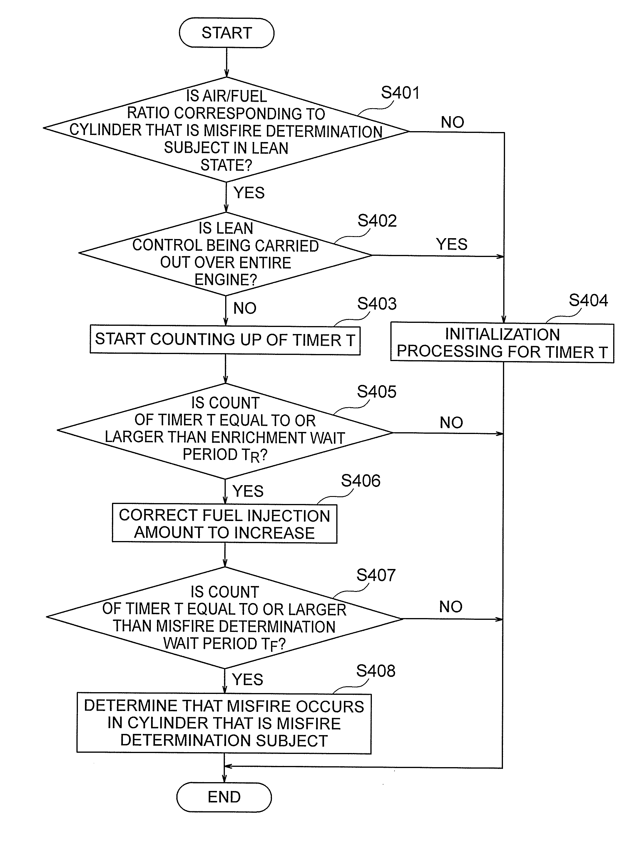
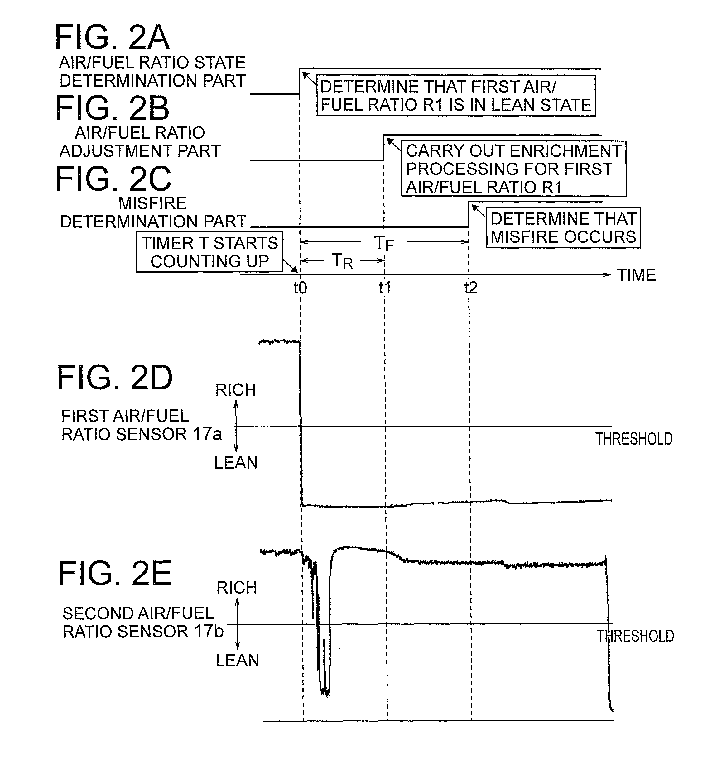
Provided are a misfire detection apparatus and a misfire detection method for an internal combustion engine, which are capable of correctly detecting a misfire state of an engine for a vehicle small in number of cylinders and in rotational inertia without limiting control to O2 feedback control. When an air / fuel ratio of an exhaust gas exhausted from a cylinder that is a misfire determination subject is in a lean state, and when lean control is not being carried out on the internal combustion engine, enrichment processing for the air / fuel ratio is carried out. When the air / fuel ratio remains in the lean state even though the enrichment processing is carried out, it is determined that misfire occurs in the cylinder that is a misfire determination subject.

Description

BACKGROUND OF THE INVENTION[0001]1. Field of the Invention[0002]The present invention relates to a misfire detection apparatus and a misfire detection method for an internal combustion engine, which are applicable to an internal combustion engine including a plurality of cylinders, for determining presence / absence of misfire in each of the plurality of cylinders.[0003]2. Description of the Related Art[0004]In recent years, detection of a misfire state in an internal combustion engine (hereinafter also referred to as engine) has been demanded as environmental measures in order to prevent unburned gas from being exhausted, and to protect a catalyst provided on an exhaust system of the engine on four-wheeled vehicles as well as two-wheeled vehicles.[0005]On this occasion, as a first measure for detecting the misfire state of the engine, there is a measure for monitoring a change in an r.p.m. of an engine (r.p.m. of a crankshaft), and detecting a misfire state of the engine based on the...

Claims


Application Information

Patent Timeline
Patent Type & Authority Patents(United States)
IPC IPC(8): G01M15/11F02D41/22F02D41/40
CPCG01M15/11F02D41/22F02D41/40F02D2200/1015
Inventor WADA, SHUICHI
Owner MITSUBISHI ELECTRIC CORP
Learn More