
Keyboard device for electronic keyboard instrument

a keyboard and electronic keyboard technology, applied in the field of electronic keyboard instruments, can solve the problems of insufficient relationship between the hammer engaged with the fulcrum shaft portion and the associated switch body of the key switch mounted to the stopper mounting portion, inability to obtain proper key depression information, and inability to achieve high dimensional accuracy. , to achieve the effect of excellent tone generation and high accuracy

Active Publication Date: 2013-07-18
KAWAI MUSICAL INSTR MFG CO
View PDF13 Cites 11 Cited by
  • Summary
  • Abstract
  • Description
  • Claims
  • Application Information

AI Technical Summary

Benefits of technology

The present invention provides a keyboard device for an electronic keyboard instrument that allows for high accuracy in setting the position between hammers and a key switch, ensuring proper detection of key depression information and excellent tone generation. Additionally, the device provides flexibility in coping with changes in key length and position, improving design flexibility and maintaining uniformity in key touch feeling.

Problems solved by technology

However, in the above-described keyboard device, since the hammer rail is formed by an extrusion molded article of aluminum, the demanded high dimensional accuracy cannot be sufficiently obtained.
In this case, even if the variation is minute (e.g. 0.1 mm or so), proper relationship between the hammer engaged with the fulcrum shaft portion and the associated switch body of the key switch mounted to the stopper mounting portion may not be obtained.
In this case, proper key depression information cannot be obtained, which makes it impossible to ensure proper tone generation.
For this reason, e.g. as to the length of a portion of the key extending forward from the swing fulcrum of the key, an allowable range of setting is limited within the dimension of the front chassis in the front-rear direction, and therefore the degree of freedom in designing the keyboard device is not large enough.
For this reason, when an impact is applied to the keyboard device e.g. due to careless dropping of the electronic piano during transportation of the same, a portion of the front chassis between the adjacent metal reinforcement beams around the keyframe center can be warped downward, resulting in permanent deformation thereof.
Thus, the above-described keyboard device leaves room for improvement.

Method used


Image

  • Keyboard device for electronic keyboard instrument
  • Keyboard device for electronic keyboard instrument
  • Keyboard device for electronic keyboard instrument

Examples


Embodiment Construction

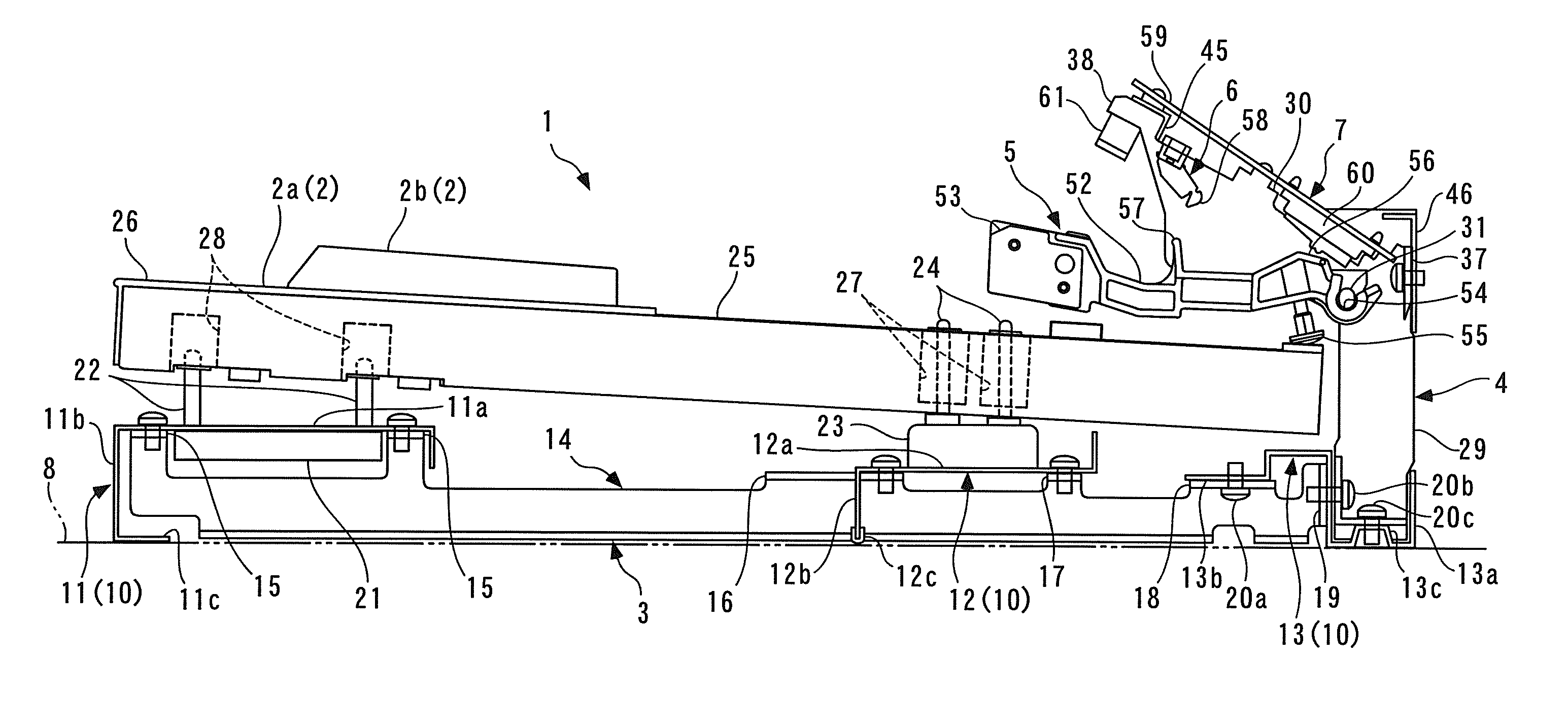
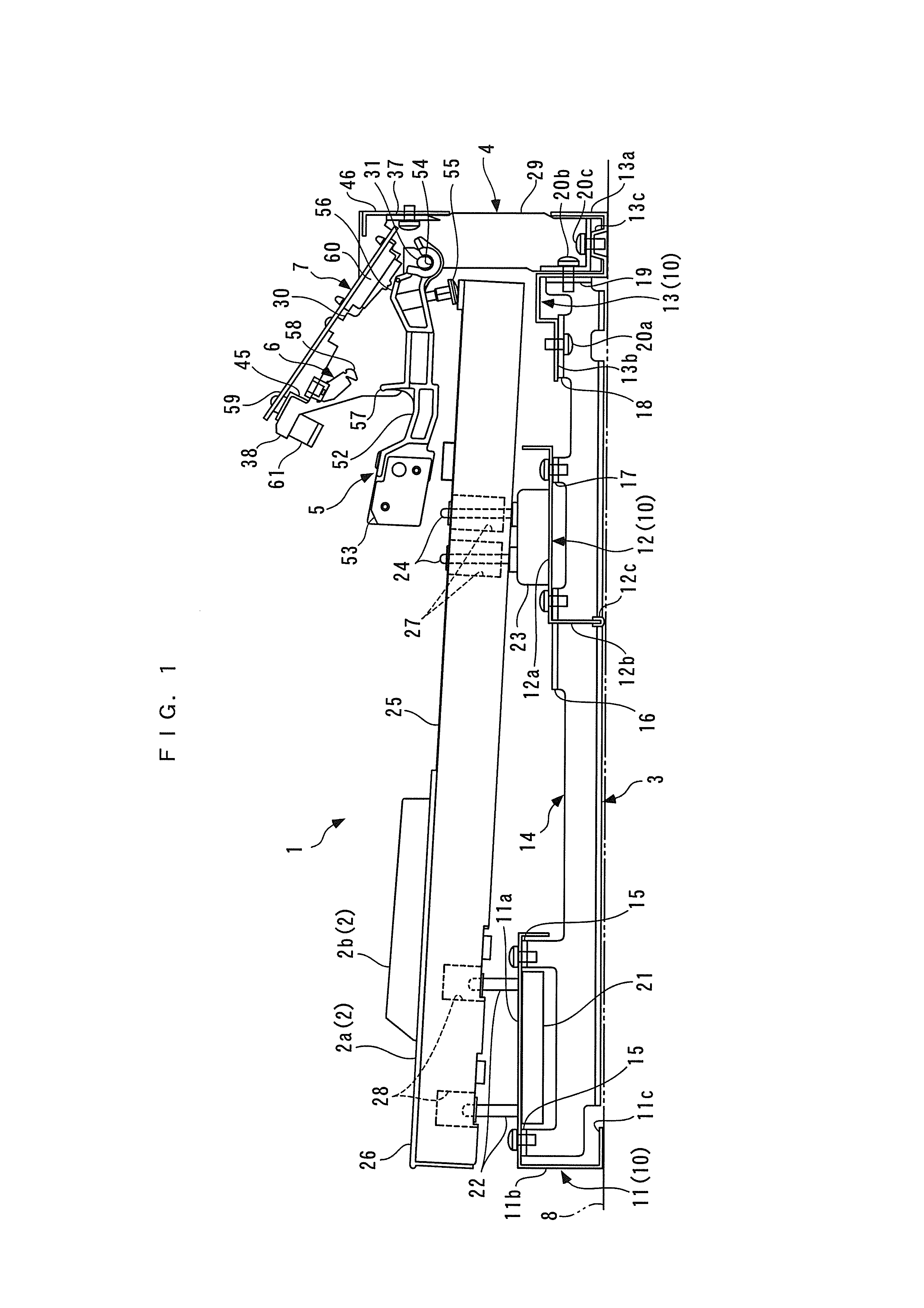
[0047]The present invention will now be described in detail with reference to the drawings showing a preferred embodiment thereof. FIG. 1 shows a keyboard device for an electronic piano in a key-released state, according to the embodiment of the present invention.

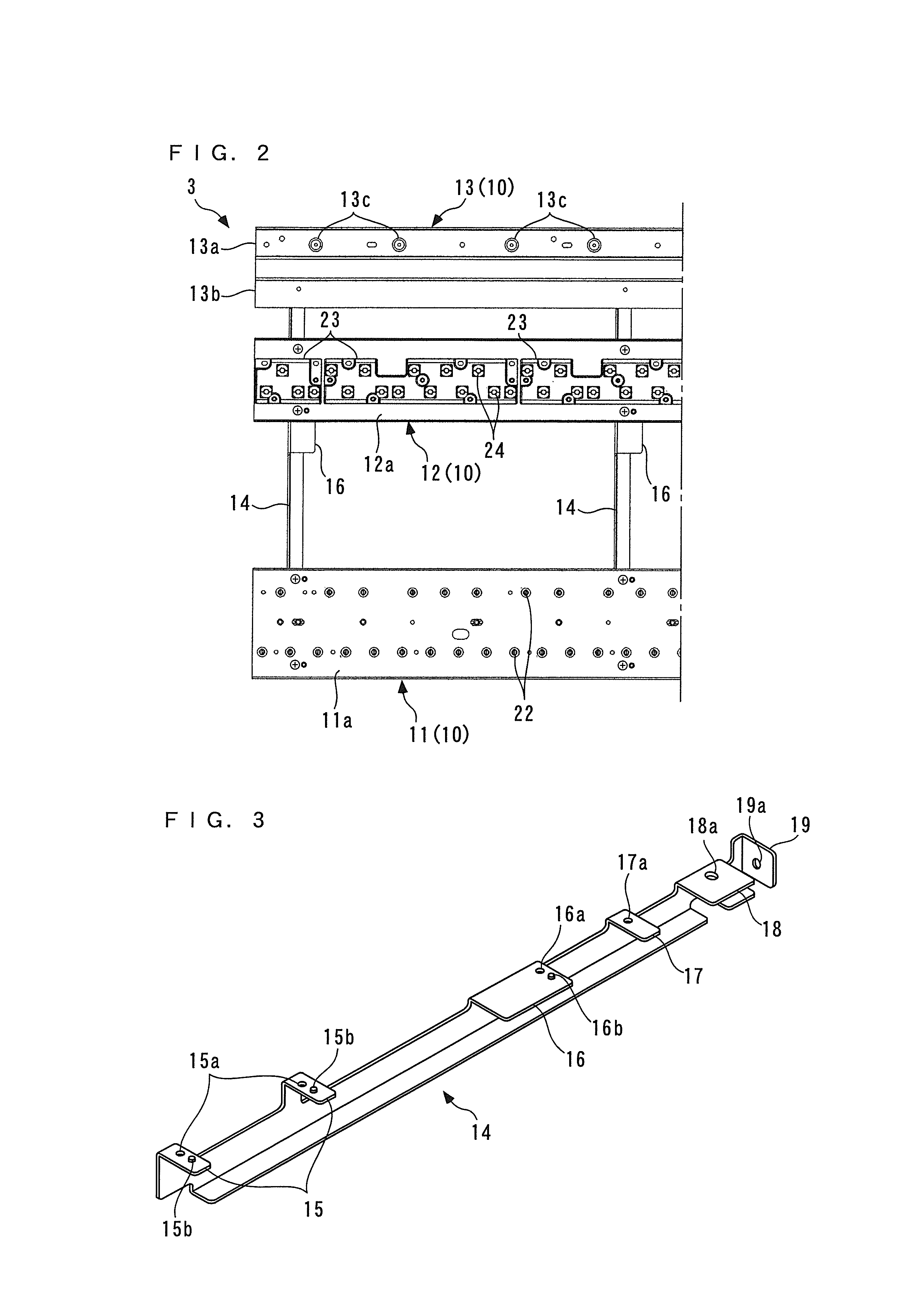
[0048]As shown in FIG. 1, the keyboard device 1 includes a plurality of keys 2 (only one of white keys 2a and one of black keys 2b are shown) arranged side by side in the left-right direction (front-rear direction as viewed in FIG. 1) of the electronic piano, a keyboard chassis 3 for supporting the keys 2, hammer supports 4 connected to the rear end (right end as viewed in FIG. 1) of the keyboard chassis 3, a plurality of hammers 5 (only one of which is shown) each provided for an associated one of the keys 2, for pivotal movement in accordance with depression of the key 2, a plurality of let-off members 6 (only one of which is shown) each provided for an associated one of the hammers 5 so as to add a let-off feeling to the...


PUM


Abstract

A keyboard device for an electronic keyboard instrument, including several keys arranged side by side in a left-right direction, a hammer support disposed rearward of the keys, a plurality of hammers pivotally supported by the hammer support to be pivotally moved in accordance with key depression, and a key switch having a plurality of switch bodies provided in association with the respective hammers and a switch board mounted to the hammer support. The hammer support has a hammer supporting part for supporting the hammers and a switch mounting part to which the key switch is mounted, and is formed by an injection molded article of a predetermined kind of synthetic resin.

Description

BACKGROUND OF THE INVENTION[0001]1. Field of the Invention[0002]The present invention relates to a keyboard device for an electronic keyboard instrument, such as an electronic piano.[0003]2. Description of the Related Art[0004]Conventionally, as a keyboard device for an electronic piano, there has been known one disclosed e.g. in Japanese Patent Laid-Open Publication No. 2002-116760 filed by the present applicant. The keyboard device comprises a plurality of swingable keys, a plurality of hammers provided in association with the respective keys for pivotal movement in accordance with key depression, and a hammer rail for pivotally supporting the hammers. Each of the hammers is formed into an arm-like shape extending in the front-rear direction of the keyboard device, and has a rear end thereof formed with a shaft hole having a C shape in side view and a lower surface thereof provided with an adjustment screw at a location immediately forward of the shaft hole. The hammer rail is for...

Claims


Application Information

Patent Timeline
Patent Type & Authority Applications(United States)
IPC IPC(8): G10H1/34
CPCG10H1/34G10C3/12G10H1/346
Inventor ISHIDA, HIDEYUKI
Owner KAWAI MUSICAL INSTR MFG CO
Learn More