Internal combustion engine cooling device

Active Publication Date: 2013-07-18
NIPPON THERMOSTAT
View PDF11 Cites 14 Cited by
  • Summary
  • Abstract
  • Description
  • Claims
  • Application Information

AI Technical Summary

Benefits of technology

The present invention provides an insulating cover for an internal combustion engine cooling device that reduces thermo-sensitivity to cooling water and simplifies the structure, thereby minimizing the effect of cooling water on the control of the main valve. This is achieved by using a resinous insulating material and a multi-layered structure that includes a layer of air to surround the thermo-sensitive portion. The invention also reduces the necessary electric power and the time it takes to achieve the desired temperature, resulting in an energy-saving effect. Overall, this invention provides a more reliable and cost-effective solution for controlling the cooling of an internal combustion engine.

Problems solved by technology

In that case, however, the wax is too easily affected by the cooling water temperature at low temperatures and does not easily heat up even with the use of a heater.
In addition, compared to the case itself, which has thick walls, the cover that makes the case thin is lightweight.
The friction of contact between the main valve spring made of metal and the bypass valve spring made of metal, on the one hand, and the thermal insulation cover made of resin on the other damages or destroys the cover, with the possibility that pieces of resin get into the coolant circuit.
But doing so raises a structural problem in the form of an increase in the number of components, and this point too must be given consideration.

Method used


Image

  • Internal combustion engine cooling device
  • Internal combustion engine cooling device
  • Internal combustion engine cooling device

Examples


Embodiment Construction

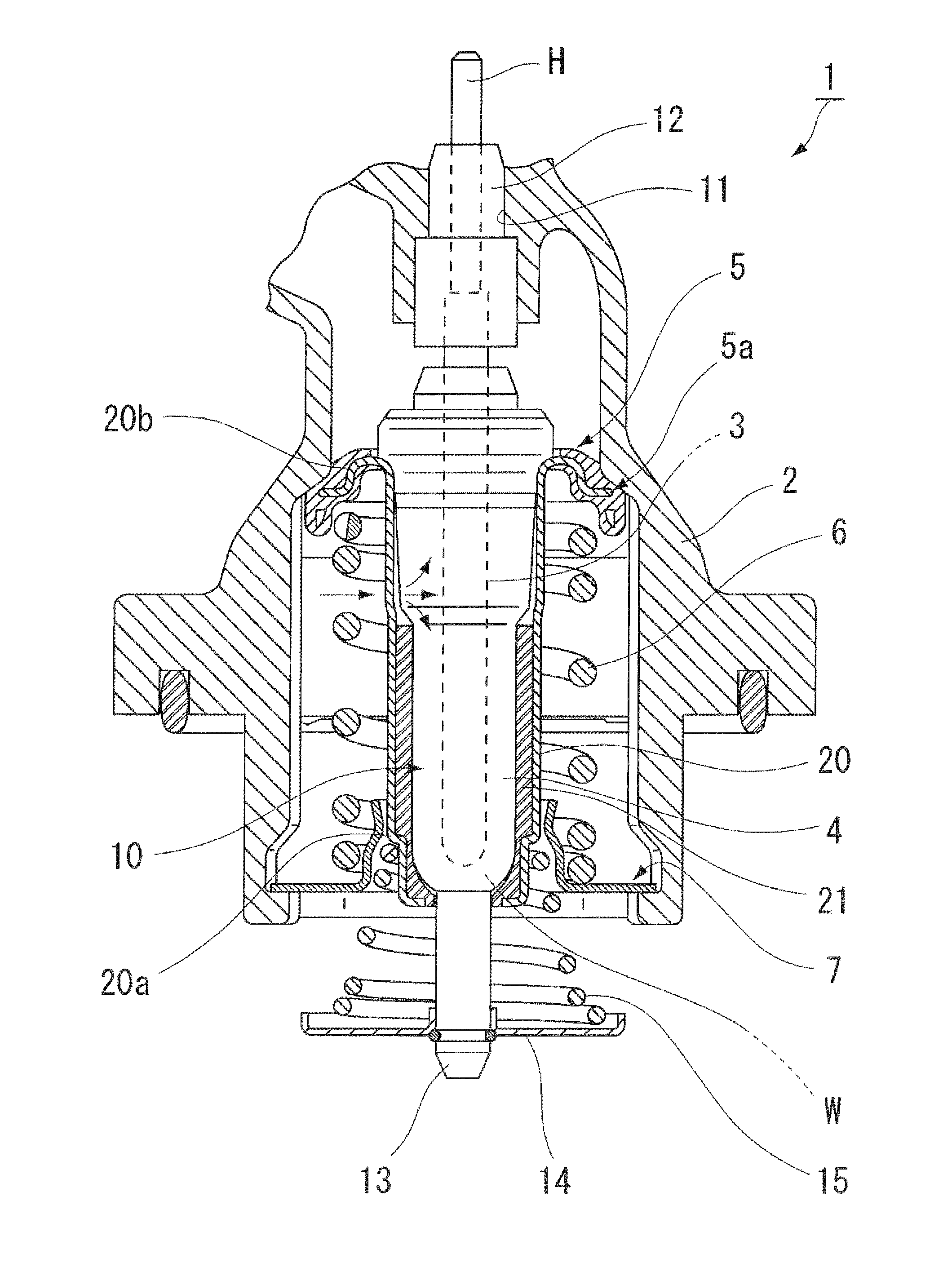
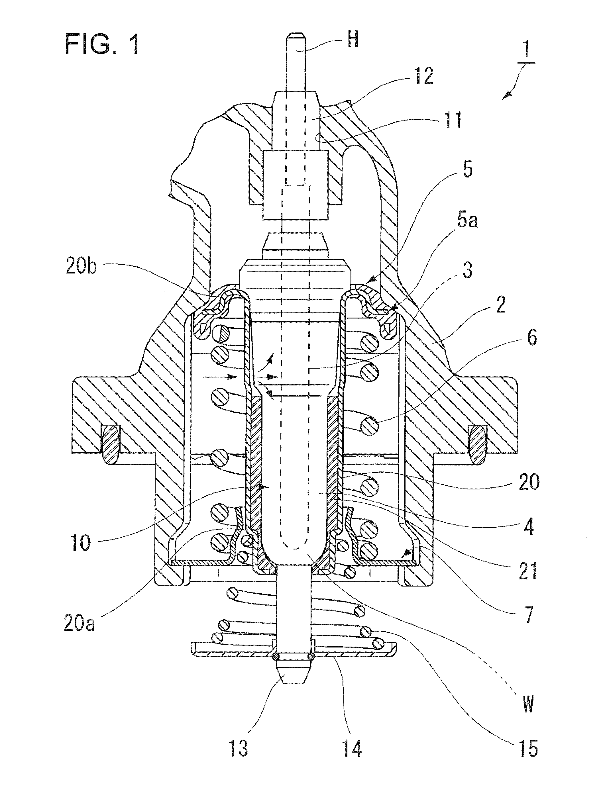
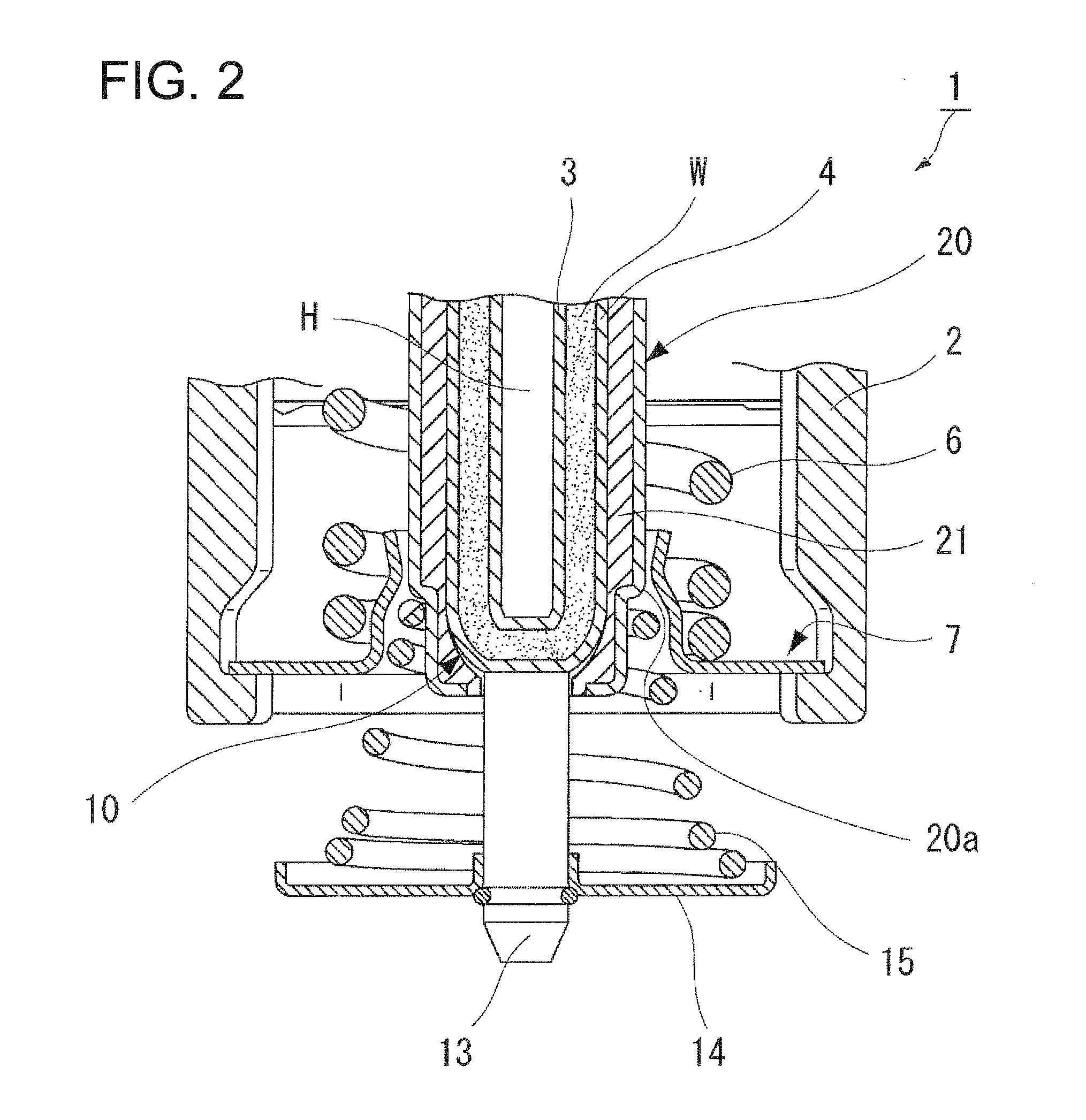
[0030]FIG. 1 and FIG. 2 show one embodiment of an internal combustion engine cooling device according to the present invention.

[0031]In these drawings, the thermostat device, which is designated as a whole by reference numeral 1, is installed inside a device housing (hereinafter referred to as simply housing) 2 that is linked to a plurality of flow paths through which cooling water flows, and functions to open and close the flow paths by operating a valve.

[0032]The thermostat device 1 is provided with a piston 3 fixed within the housing 2 in a vertically suspended state and a cylinder container (thermo-element case) 4 that advances and retreats relative to the piston 3. The thermostat device 1 is further provided with a flange valve 5 that is formed around the outside of the top end of the cylinder container 4 and which opens and closes the main flow path of the water cooling water, a spring 6 that is wound around the cylinder container 4 and one end of which contacts the back of th...


PUM


Abstract

[Problem] To obtain a thermostat device with which it is possible to dull the thermosensitivity of a thermo-element thermosensitive component to coolant water and better control the opening and closing of a main valve at a selected timing by means of an electrical heater. [Solution] A thermostat device (1) comprises: a piston (3); a cylinder container (4) which operates forward and reverse with respect to the piston and further comprises a flange valve which opens and closes a main flow path of coolant water; a thermal expansion body (W) which causes the cylinder container to operate forward and reverse upon the piston with a volumetric change commensurate with a temperature change within said cylinder container; and a thermo-element assembly body (10) which is disposed within the piston and further comprises a heat emitting element (H) which applies heat to the thermal expansion body by a supply of electricity. An insulating cover (20) is disposed which is formed to cover the exterior side portion of the cylinder container which faces the coolant water. Additionally, a resinous insulating material (21) and / or an atmosphere layer (22) are selectively disposed on the interior side of the insulating cover between said insulating cover and the exterior side face of the cylinder container.

Description

BACKGROUND OF THE INVENTION[0001]1. Technical Field[0002]The present invention relates to a thermostat device as a cooling device of an internal combustion engine (hereinafter referred to as an engine) that variably controls water temperature in a water-cooled temperature control system that variably controls the cooling water temperature of an engine for use in an automobile or the like, for example, and more particularly, to a mounting structure for a device housing of a thermo-element assembly thereof.[0003]2. Background Art[0004]For example, a thermostat device installed in a water-cooled system of an engine has a built-in thermal expansion unit (wax) that senses changes in temperature of the cooling water flowing through a circulatory flow path and expands and contracts accordingly. The thermostat device opens and closes a valve using volumetric changes attendant upon the expansion and contraction of the wax and functions to maintain the cooling water at a predetermined tempera...

Claims


Application Information

Patent Timeline
IPC IPC(8): F01P7/16
CPCF01P7/167F01P2070/04F16K31/002F01P7/16F16K31/025G05D23/125G05D23/12G05D23/123G05D23/022
Inventor NAKAJIMA, TADAOSUZUKI, TOSHITAKA
Owner NIPPON THERMOSTAT
Why Eureka
Try Eureka