Mobile phone terminal with remote control function

Inactive Publication Date: 2011-09-15
SHINTEN SANGYO
View PDF7 Cites 68 Cited by
  • Summary
  • Abstract
  • Description
  • Claims
  • Application Information

AI Technical Summary

Benefits of technology

[0009]The present invention is conceived in view of the above-described circumstances, and provides a novel mobile phone terminal with remote control function capable of switching between and display

Problems solved by technology

However, under these circumstances the number and types remote controls tends to proliferate.
Moreover, each device operates differently, which complicates operation and causes problems in terms of operability.
However, the required operating butto

Method used


Image

  • Mobile phone terminal with remote control function
  • Mobile phone terminal with remote control function
  • Mobile phone terminal with remote control function

Examples


Example

[0018]Preferred embodiments of the present invention will now be described in detail, with reference to the accompanying drawings.

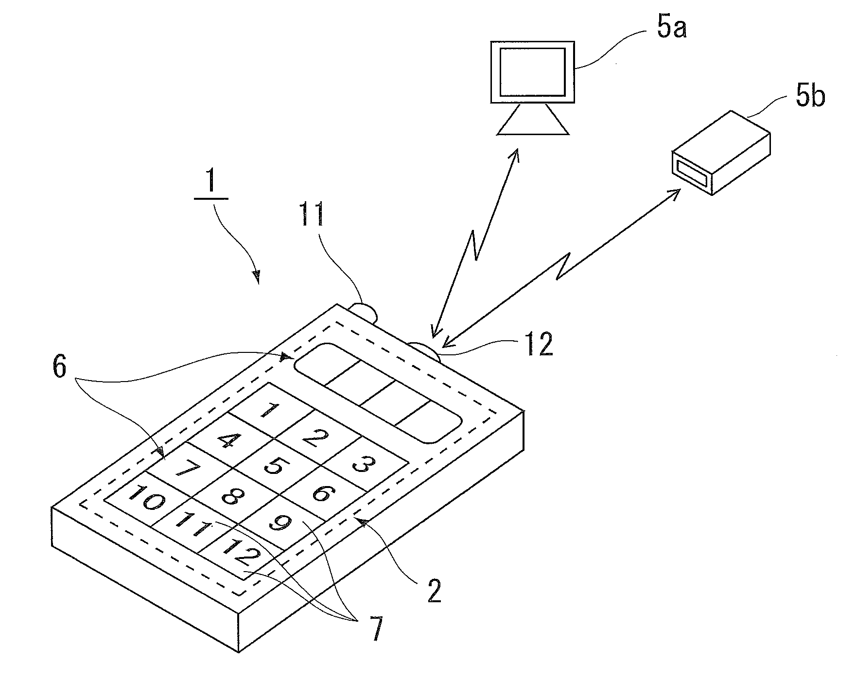
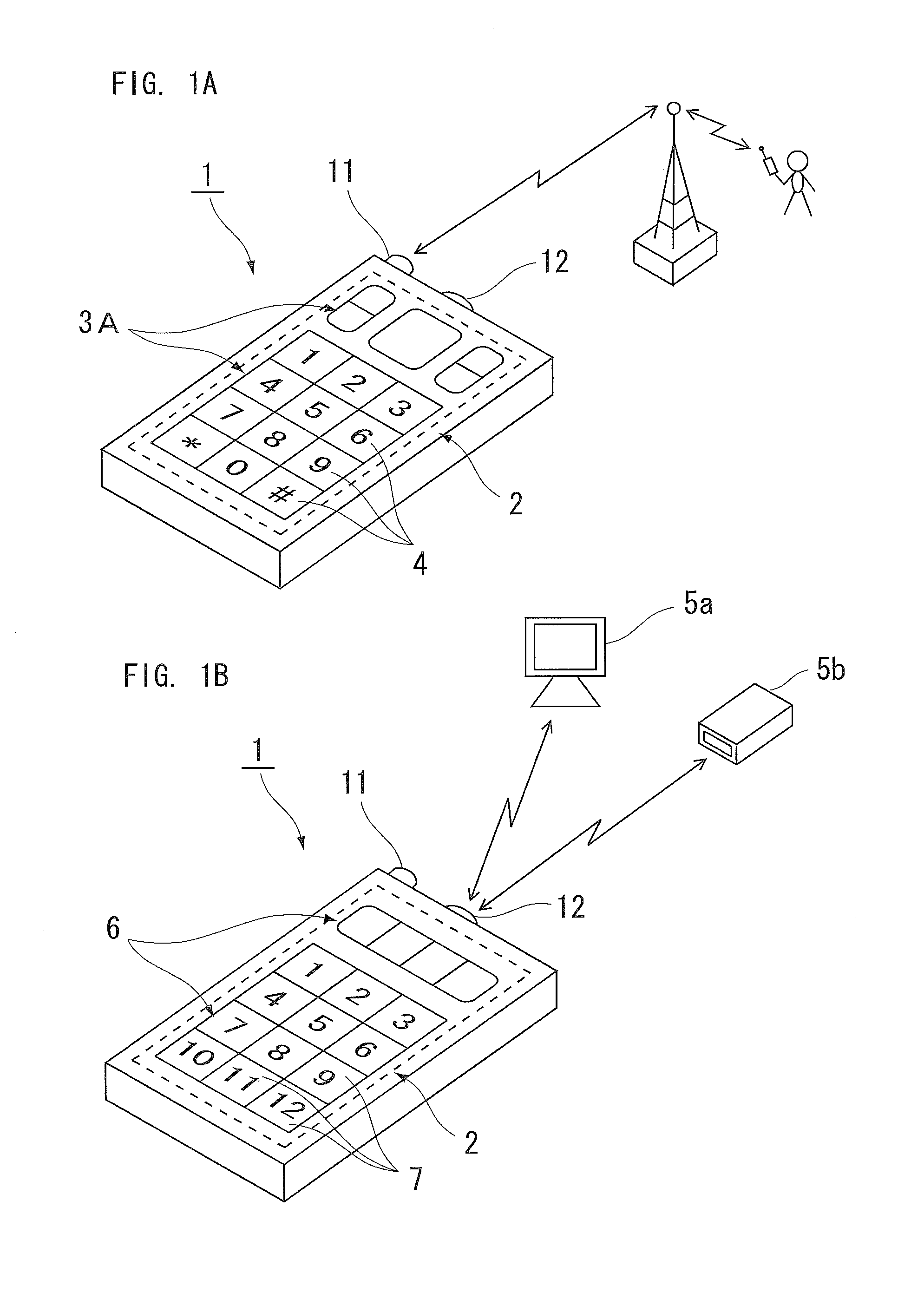
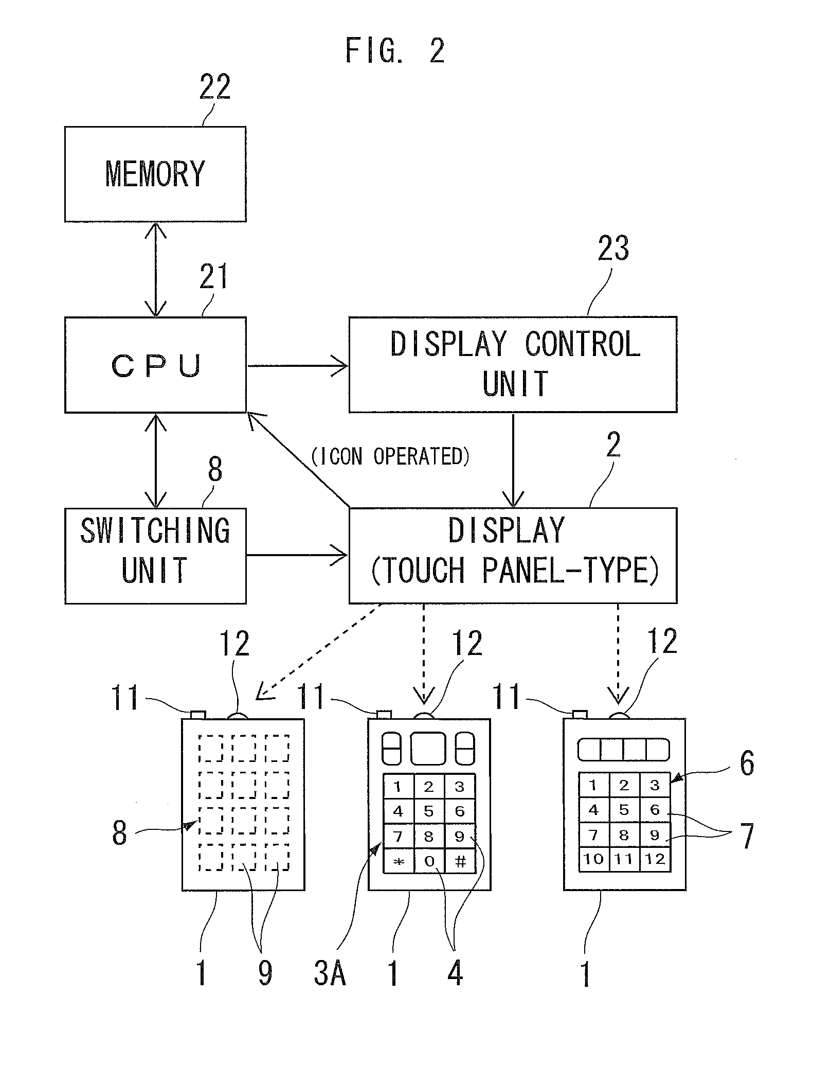
[0019]FIG. 1 and FIG. 2 show a mobile phone terminal with remote control function according to one embodiment of the present invention.

[0020]In FIGS. 1 and 2, reference numeral 1 designates a mobile phone terminal that is equipped with a touch panel display 2. The mobile phone terminal 2 is configured so as to display on the display 2 a display pattern for a phone function 3A as shown in FIG. 1A, for making the mobile phone function as a phone.

[0021]Further, the mobile phone terminal 1 has additional function display patterns 3B, 3C, . . . 3n that serve as displays for operating, in addition to the phone function, such other functions as a PDA, audio player, camera, video player, game player, internet terminal, personal computer, GPS receiver, and so forth.

[0022]The respective display patterns 3B, 3C . . . 3n are installed as convenient and each one inclu...


PUM


Abstract

A mobile phone terminal with remote control function including a touch panel display and configured to selectively display function display patterns having a plurality of operating icons representing multiple functions including a phone function on the touch panel display, in which the mobile phone terminal has a display unit that displays a remote-control function display pattern for operating one or more external devices by remote control and a switching unit that selectively switches the remote-control function display pattern.

Description

CROSS-REFERENCE TO RELATED APPLICATIONS[0001]The present patent application claims priority from Japanese Patent Application No. 2010-85522, filed on Mar. 15, 2010, which is hereby incorporated herein by reference in its entirety.BACKGROUND OF THE INVENTION[0002]1. Field of the Invention[0003]The present invention relates to a mobile phone terminal equipped with a remote control function, and more particularly, to a mobile phone terminal equipped with a remote control function capable of remotely controlling a variety of external devices, such as a television, air conditioner, audio device, personal computer, or the like.[0004]2. Description of the Related Art[0005]Handheld electronic devices that have multi-touch input screens on the face of the device and which are used as mobile phones have been proposed, for example, in Japanese Patent Application Publication No. 2008-537615 (JP-2008-537615-A).[0006]At the same time, in ordinary homes and the like, remote control devices (herein...

Claims


Application Information

Patent Timeline
IPC IPC(8): H04M3/00H04B1/38H04M1/00H04M1/72415H04N5/00H04N5/44
CPCG08C17/02H04M1/72533G08C2201/93G08C23/04H04M1/72415
Inventor HIRAIDE, YOSHIFUMI
Owner SHINTEN SANGYO
Why Eureka
Try Eureka