Force feedback input device

Inactive Publication Date: 2005-01-13
ALPS ALPINE CO LTD
View PDF6 Cites 19 Cited by
  • Summary
  • Abstract
  • Description
  • Claims
  • Application Information

AI Technical Summary

Benefits of technology

[0008] Accordingly, it is an object of the present invention to provide a force feedback input device that can limit the excessive displacement of an operation member at a stopper position while providing a wall effect, can appropriately change the stopper position, and can reduce power consumption.
[0010] In the force feedback input device including the stopper means with the ratchet mechanism, at the moment when the detection means detects the displacement of the operation member that is exceeding the allowed operation limit, the ratchet of the stopper means is engaged with the corresponding gear teeth. As a result, this instantly restricts excessive displacement of the operation member while allowing the operation member to be displaced in the opposite direction (a “push back” operation) and, therefore, produces a wall effect and superior operability. Additionally, since a large electric current is not required for disengaging the ratchet from the gear teeth, the stopper means can be operated at low power consumption. Furthermore, if the allowed operation range of the operation member is altered, a stopping position of the operation member can be readily changed by controlling a driving signal for the ratchet mechanism of the stopper means.
[0011] In the force feedback input device, the gear teeth of the ratchet mechanism in the stopper means are preferably mounted on the operation member, and thereby the ratchet mechanism has a simple and reliable structure in which a ratchet is disengaged from the gear teeth movable along with the operation member.
[0012] Additionally, in the force feedback input device according to the present invention, the ratchet mechanism of the stopper means may include a first ratchet for restricting displacement of the operation member in one direction and a second ratchet for restricting displacement of the operation member in the opposite direction. The first ratchet can be engaged with corresponding gear teeth when the operation member is operated and is displaced to the allowed limit of the operation range in one direction. Also, the second ratchet can be engaged with corresponding gear teeth when the operation member is operated and is displaced to the allowed limit of the operation range in the opposite direction. Accordingly, the movement of the operation member can be reliably restricted at both ends of the operation range with a wall effect.

Problems solved by technology

Unfortunately, in the case where the allowed operations range, namely, moving range of the operation member varies in accordance with use conditions, a stopper mechanism capable of changing the position of the stopper is essential to restrict excessive displacement of the operation member.
However, since the known force feedback input device must apply a large electric current every time the operation member is displaced to an allowed limit of the operation range, power consumption is undesirably increased, which is a problem.
In addition, the control method that increases the resistance force by applying a large electric current to the motor does not produce a distinct sense indicating that no more displacement of the operation member is possible, also referred to as “wall effect”.
Consequently, this method does not provide satisfactory operability.
As a result, the braking force of the electromagnetic brake must not be too strong and, therefore, this force feedback input device cannot provide satisfactory operability.

Method used


Image

  • Force feedback input device
  • Force feedback input device

Examples


Embodiment Construction

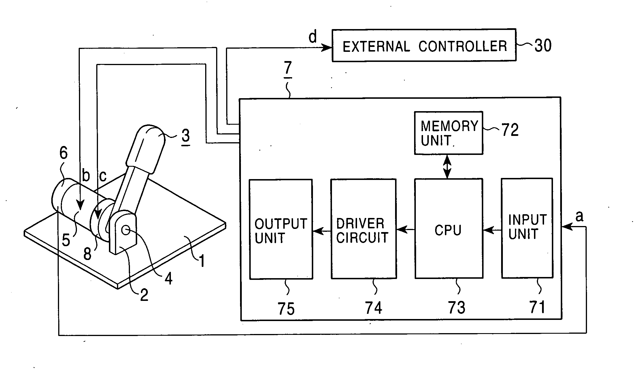
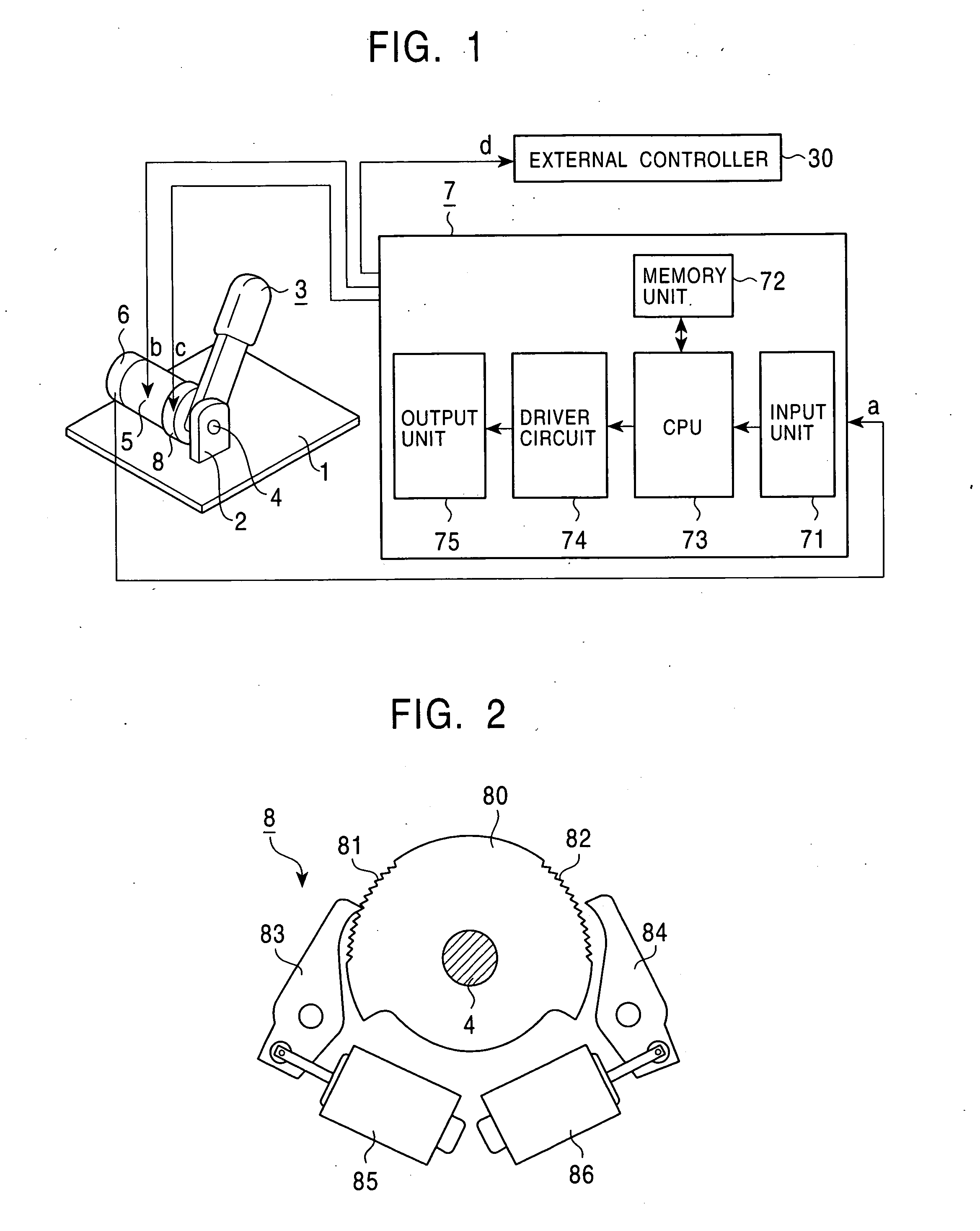
[0015] An embodiment of the present invention will now be described with reference to the accompanying drawings. FIG. 1 is a block diagram of the entire force feedback input device according to the embodiment. FIG. 2 is a view of a relevant portion of stopper means in the force feedback input device.

[0016] In the force feedback input device according to the embodiment, an operation member is pivotally operated by hand. The force feedback input device includes a support plate 1; a bearing 2 fixedly mounted on the support plate 1; an pivotally movable operation member 3 with a protruding shaft 4 rotatably supported by the bearing 2; an actuator 5 which provides force feedback to the operation member 3, a rotary encoder 6 which detects the operating status of the operation member 3; control means 7 which outputs driving signals b and c, and a command signal d based on a detection signal a from the rotary encoder 6; and stopper means 8 which limits displacement of the operation member ...


PUM


Abstract

A force feedback input device includes an operation member having a shaft and operated by an operator, detection means, such as a rotary encoder, for detecting an operating status of the operation member, an actuator for providing force feedback to the operation member, control means for controlling the actuator based on a detection signal output from the detection means, and stopper means for restricting displacement of the operation member in a predetermined operational direction. The stopper means includes a ratchet mechanism to disengage ratchets from corresponding gear teeth in response to the detection signal from the detection means.

Description

BACKGROUND OF THE INVENTION [0001] 1. Field of the Invention [0002] The present invention relates to a force feedback input device in which force feedback is provided to an operation member of the force feedback input device in accordance with the operating status and, in particular, to a stopper mechanism to restrict excessive displacement of the operation member. [0003] 2. Description of the Related Art [0004] As input devices applied to, for example, a central “by-wire” control system of in-car electronic devices, a steer-by-wire steering system, a shift-by-wire gear change system, and a brake-by-wire braking system, force feedback input devices are known which includes an operation member that an operator manually operates, detection means, such as a position sensor, for detecting the operating status of the operation member, an actuator for providing force feedback to the operation member, and control means for controlling the actuator based on detection signals output from the...

Claims


Application Information

Patent Timeline
IPC IPC(8): F16H31/00G06F3/06B25J13/02
CPCG05G1/04G05G5/03Y10T74/19251G06F3/016G06F3/0338G05G5/24
Inventor KOBAYASHI, AYUMUSHIBAZAKI, KENFUKUSHIMA, NORIYUKI
Owner ALPS ALPINE CO LTD
Why Eureka
Try Eureka