Valve timing control apparatus for internal combustion engine

a timing control and internal combustion engine technology, applied in mechanical equipment, valve arrangements, machines/engines, etc., can solve problems such as layout limitations, and achieve the effect of enhancing the freedom of engine layou

Active Publication Date: 2013-07-18
HITACHI ASTEMO LTD
View PDF9 Cites 21 Cited by
  • Summary
  • Abstract
  • Description
  • Claims
  • Application Information

AI Technical Summary

Benefits of technology

[0025]The valve timing control apparatus for an internal combustion engine, according to the present invention, can enhance a freedom of layout in the engine by using a lock pin having a minimum size which is locked in an intermediate phase position between a maximum phase-retard position and a maximum phase-advance position.

Problems solved by technology

Therefore, it is necessary to ensure a large space for accommodating the lock pin, thereby causing limitation in layout.

Method used


Image

  • Valve timing control apparatus for internal combustion engine
  • Valve timing control apparatus for internal combustion engine
  • Valve timing control apparatus for internal combustion engine

Examples


first embodiment

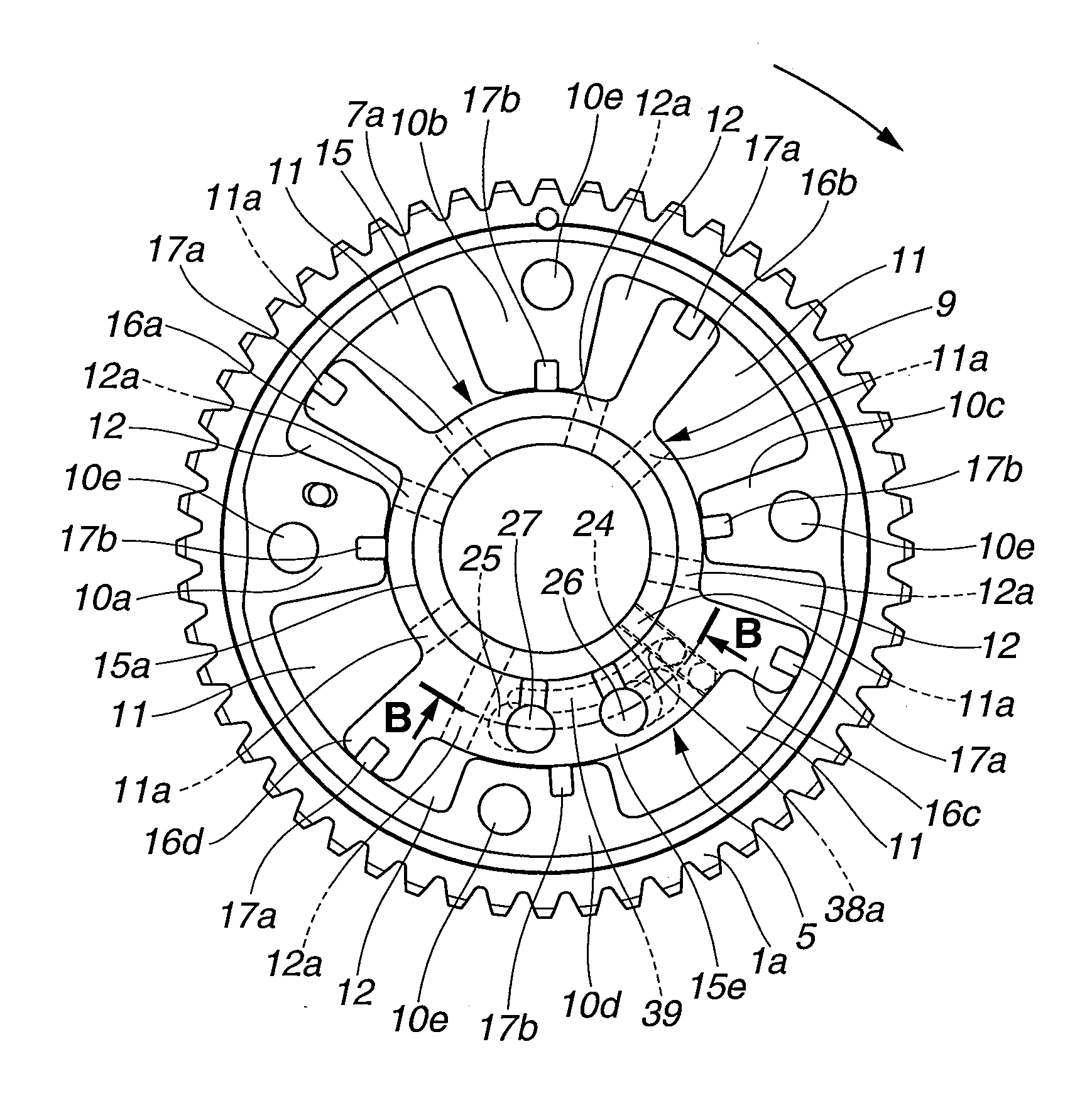
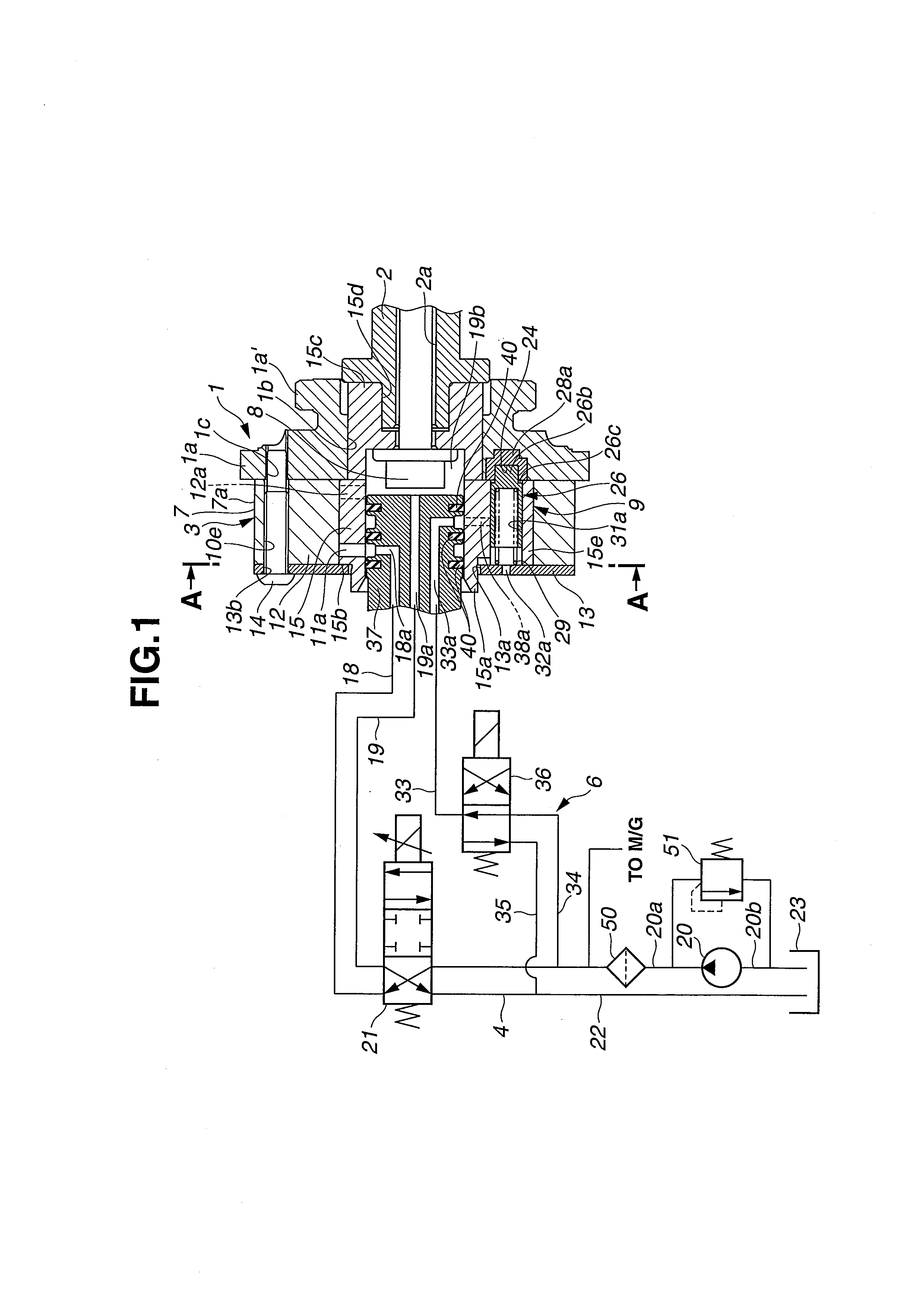
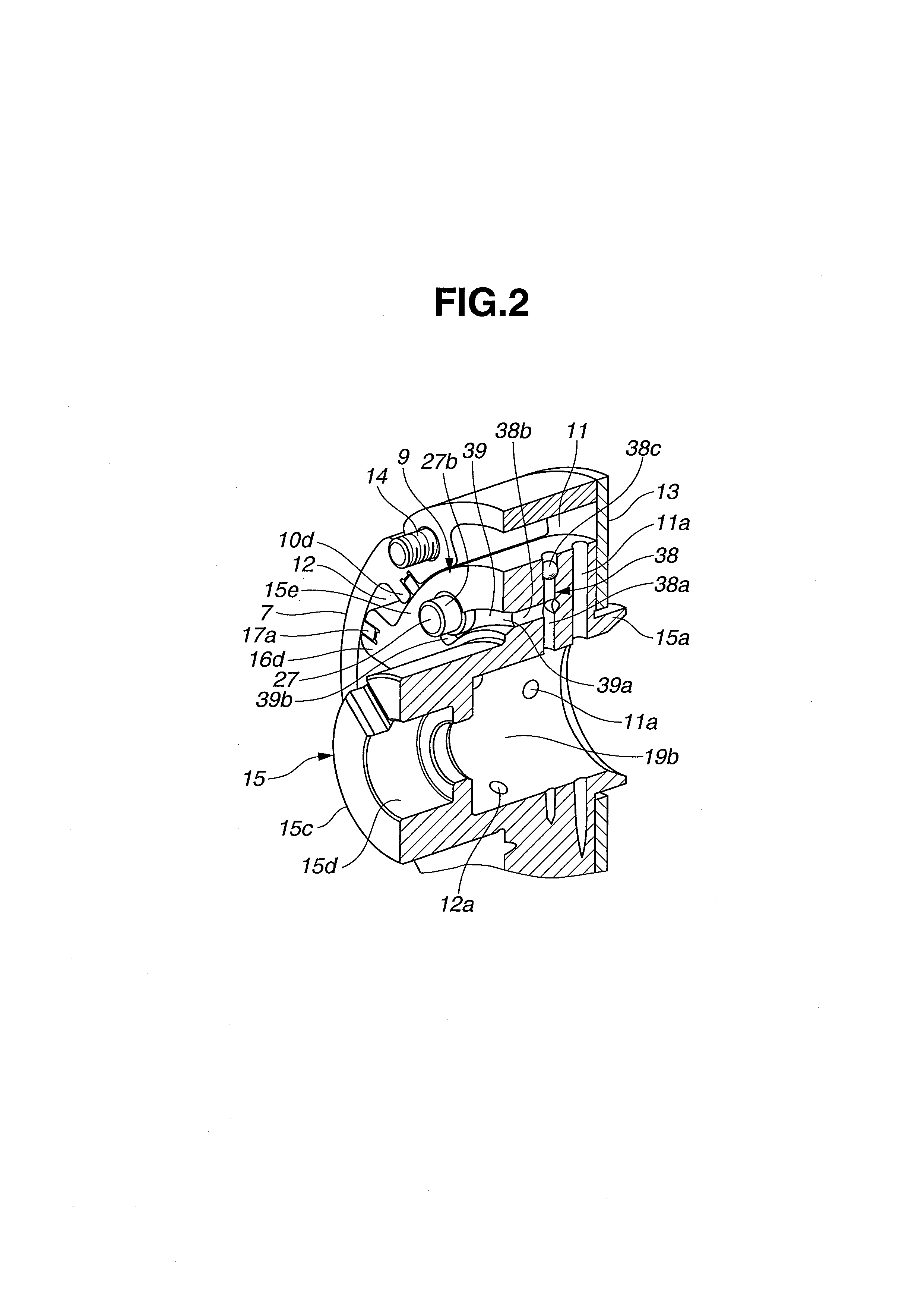
[0039]Referring to FIG. 1 to FIG. 10, there is shown a valve timing control apparatus according to a first embodiment of the present invention. As shown in FIG. 1, valve timing control apparatus 100 includes sprocket 1 as a drive rotation member, intake-side camshaft 2 disposed to be rotatable relative to timing sprocket 1, phase varying mechanism 3 disposed between sprocket 1 and intake-side camshaft 2 and serving to vary a relative rotational phase thereof, first hydraulic circuit 4 that serves to operate phase varying mechanism 3, position holding mechanism (i.e., lock mechanism) 5 that holds a rotational position of camshaft 2 relative to sprocket 1 in a predetermined intermediate phase position between a maximum phase-retard position and a maximum phase-advance position through phase varying mechanism 3, and second hydraulic circuit 6 that serves to operate position holding mechanism 5. Sprocket 1 is rotationally driven by a crankshaft of the engine through a timing chain. Inta...

second embodiment

[0114]Referring to FIG. 11, there is shown a valve timing control apparatus according to a second embodiment of the present invention, in which first lock pin 26 and second lock pin 27 of position holding mechanism 5 are arranged in a diametrically opposed relation to each other with respect to the central axis of rotor 15.

[0115]As shown in FIG. 11, rotor 15 of valve timing control apparatus 200 includes first large-diameter portion 15e and second large-diameter portion 15f disposed diametrically opposed to first large-diameter portion 15e. First pin hole 31a is formed in first large-diameter portion 15e, and second pin hole 31b is formed in second large-diameter portion 15f. First and second lock pins 26, 27 are slidably disposed in respective pin holes 31a, 31b.

[0116]On the other hand, first and second lock holes 24, 25 engageable with first and second lock pins 26, 27 respectively are formed on axial end surface 1c of sprocket 1. First lock hole 24 is configured into the same sh...


PUM


Abstract

A valve timing control apparatus including a housing, a vane rotor rotatable relative to the housing toward a phase-advance side and a phase-retard side, a first lock member and a second lock member disposed on the vane rotor, a first lock concave portion disposed on the housing so as to be engaged with a tip end portion of the first lock member, a second lock concave portion disposed on the housing so as to be engaged with a tip end portion of the second lock member, and a communication passage formed in the vane rotor and serving to always establish fluid communication between the first and second lock concave portions.

Description

BACKGROUND OF THE INVENTION[0001]The present invention relates to a valve timing control apparatus for an internal combustion engine which variably controls timings of opening and closing an engine valve (i.e., an intake valve and an exhaust valve) during an engine operation.[0002]There has been proposed a so-called vane type valve timing control apparatus for an internal combustion engine.[0003]Japanese Patent Application Unexamined Publication No. 2011-85074 discloses such a vane type valve timing control apparatus. The valve timing control apparatus of this conventional art is constructed such that when starting an engine, timings of opening and closing an intake valve is held in an intermediate phase position between a maximum phase-retard position and a maximum phase-advance position by using a lock pin to thereby enhance startability of the engine. In a case where such a lock pin is moved to an unlock position, it is preferable to allow the lock pin to retreat without adverse ...

Claims


Application Information

Patent Timeline
Patent Type & Authority Applications(United States)
IPC IPC(8): F01L1/344
CPCF01L1/34F01L1/3442F01L2001/34423F01L2001/34476F01L2001/34453F01L2001/34466F01L2001/3443
Inventor KATO, HIROYUKISATO, SHINICHI
Owner HITACHI ASTEMO LTD
Why Eureka
Try Eureka