
Exhaust system of engine

a technology of exhaust system and engine, which is applied in the direction of machines/engines, gas passages, sound absorption, etc., can solve the problems of failing to improve and achieve the effect of reducing exhaust noise and improving the output of the engin

Active Publication Date: 2013-07-18
HONDA MOTOR CO LTD
View PDF2 Cites 14 Cited by
  • Summary
  • Abstract
  • Description
  • Claims
  • Application Information

AI Technical Summary

Benefits of technology

The present invention aims to develop an exhaust system for engines that can reduce exhaust noise and enhance engine performance. The technical effect of the invention is to improve the overall output of the engine while minimizing the noise generated during the exhaust process.

Problems solved by technology

The exhaust system of the engine described in JP-A No. 2010-216340 is able to reduce exhaust noise, but fails to improve the output of the engine.

Method used


Image

  • Exhaust system of engine
  • Exhaust system of engine
  • Exhaust system of engine

Examples


Embodiment Construction

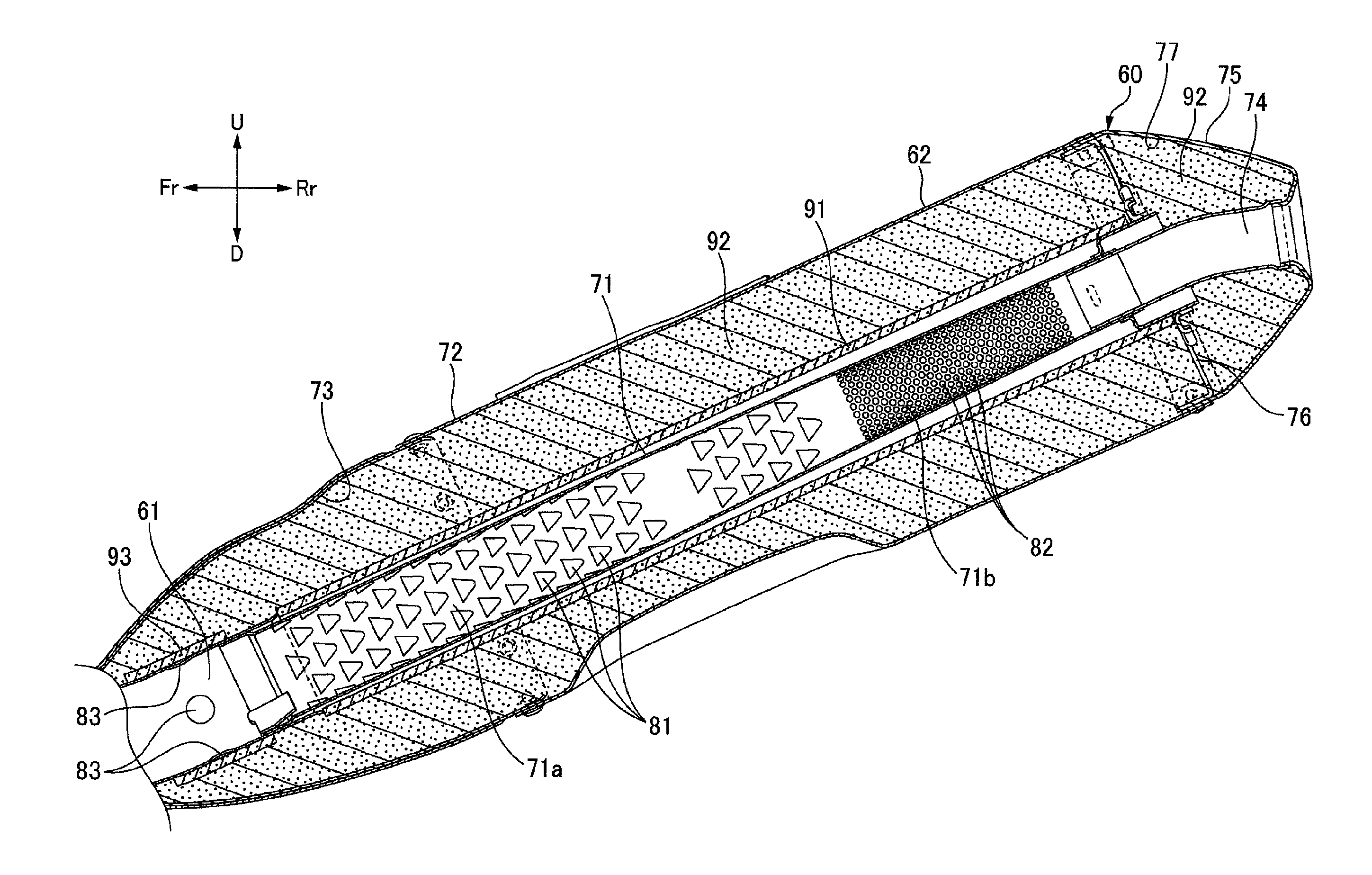
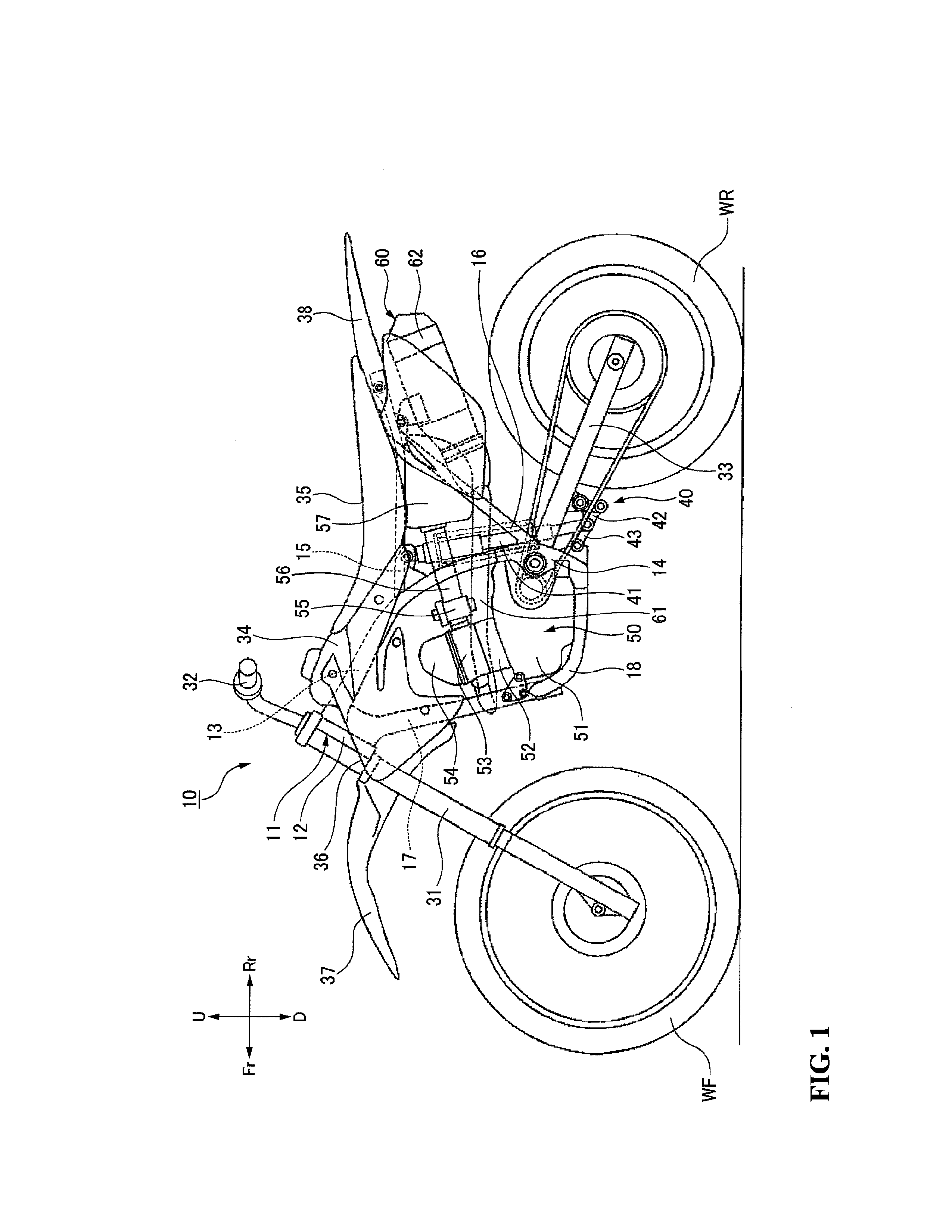
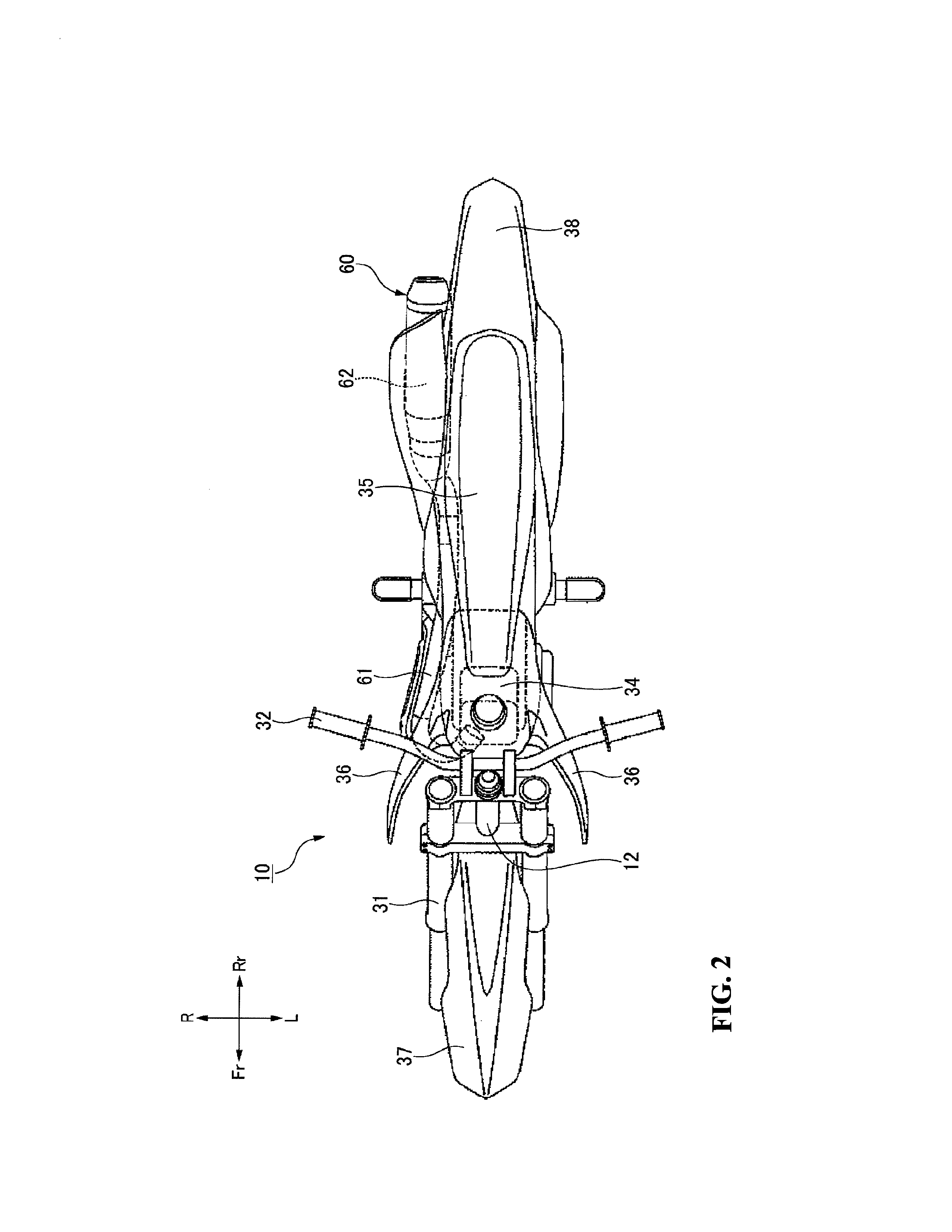
[0044]Hereinafter, an embodiment of an exhaust system of an engine according to the present invention will be described in detail with reference to the drawings. Note that the drawings are viewed based on the reference numerals, and in the following description, directions, such as front and rear, left and right, and up and down are based on a direction of a rider's view. In addition, Fr indicates a front side of a vehicle, Rr indicates a rear side of the vehicle, L indicates a left side of the vehicle, R indicates a right side of the vehicle, U indicates an upper side of the vehicle, and D indicates a lower side of the vehicle.

[0045]A motorcycle 10 of the present embodiment includes, as illustrated in FIGS. 1 and 2, a vehicle body frame 11 composed of a head pipe 12 provided at a front end, a pair of left and right main frames 13 divided from the head pipe 12 to left and right sides and extending rearwardly and downward, a pair of left and right pivot frames 14 connected to rear en...


PUM


Abstract

An exhaust system for an engine includes an exhaust pipe connected to an exhaust port of an engine and a muffler attached to the exhaust pipe and configured to reduce exhaust noise. The muffler includes an inner cylinder part connected to the downstream end of the exhaust pipe, an outer cylinder part configured to cover an outside of the inner cylinder part and noise absorbing materials disposed between the inner cylinder part and the outer cylinder part. A plurality of first communication holes providing communication between an inside and an outside of the inner cylinder part is formed in an upstream portion of the inner cylinder part. A plurality of second communication holes providing communication between the inside and the outside of the inner cylinder part is formed in a downstream portion of the inner cylinder part. Guide walls extend toward the inside of the inner cylinder part.

Description

CROSS-REFERENCE TO RELATED APPLICATIONS[0001]The present application claims priority under 35 USC 119 to Japanese Patent Application No. 2012-008079 filed Jan. 18, 2012 and Japanese Patent Application No. 2012-175125 filed Aug. 7, 2012 the entire contents of which are hereby incorporated by reference.BACKGROUND OF THE INVENTION[0002]1. Field of the Invention[0003]The present invention relates to an exhaust system of an engine.[0004]2. Description of Background Art[0005]An exhaust system of an engine includes an inner pipe provided with a plurality of vent holes connected to an exhaust pipe at an upstream end portion, an outer pipe configured to surround the inner pipe by forming an annular chamber between the inner pipe and the outer pipe and glass wool that is a noise absorbing material filled in the annular chamber, to reduce exhaust noise has been known in the related art. See, for example, JP-A No. 2010-216340.[0006]The exhaust system of the engine described in JP-A No. 2010-216...

Claims


Application Information

Patent Timeline
Patent Type & Authority Applications(United States)
IPC IPC(8): F01N1/08
CPCF01N1/082F01N13/0097F01N1/24F01N2310/02F01N2310/04F01N2470/04F01N2470/06F01N2590/04F01N13/04F01N1/026F01N1/04F01N2210/02F01N2470/02F01N2470/20F01N2470/26F01N13/1872F01N1/085F01N13/011
Inventor MATSUSHIMA, SATOSHISASAKI, TATSUYAEGUCHI, SEIICHIROISHIZAKI, HIROTSUGUHAYAMA, YOSHITAKA
Owner HONDA MOTOR CO LTD
Learn More