
Electrically controlled lock for automated sliding type gates and control method for the same

a technology of automatic sliding gate and electric control, which is applied in the direction of mechanical control, non-mechanical control, fastening means, etc., can solve the problems of not being used on automatically-operated sliding gates, abovementioned devices are not electrically controlled, and easy to jam

Active Publication Date: 2013-07-18
VIRO INNOCENTI
View PDF6 Cites 5 Cited by
  • Summary
  • Abstract
  • Description
  • Claims
  • Application Information

AI Technical Summary

Benefits of technology

The present invention provides a lock device with a burglary protection system to prevent sawing or opening the bolt shaft. The lock device has a lock encasing and a bolt with a bush for rotating the bolt shaft. There is also a fork-shaped device that moves along with the bolt and engages a hook on the cover of the encasing when the bolt is in the locked position. The technical effects are enhanced security and prevention of unauthorized access to the lock device.

Problems solved by technology

All the lock system listed in the above are characterized by a low tolerance of the position of the door in the locked state and can easily jam when the thermal dilatations of the door or the settlements of the frame induce transverse mechanical load on the bolt.
The abovementioned devices are not electrically controlled, and do not have any specific feature intended to enlarge the mechanical tolerance for the position of the door in the locked state, and in particular considering the large thermal dilatation that characterizes larger sliding gates.
It is known the patent ITBO2006A000617 (Bastianini) disclosing an electrically controlled harpoon-type snap-acting lock device capable to accept a large mechanical tolerance for the position of the door in the locked state, but can not be used on automatically-operated sliding gates due to the fact that it does not ensure a proper synchronization between the lock disengagement and the movement of the automated gate.
a) known lock devices, when applied to large sliding gates, generally do not allow a mechanical tolerance for the position of the gate in the locked state that could large enough to ensure that no lock jamming can be produced especially by thermal distortions; and
b) known lock devices, when applied to large sliding gates, generally do not comprise any specific protection device against burglary attempts carried out by trying to cut or saw the bolt element; and
c) known electrically controlled lock devices do not comprise any specific burglary protection intended to prevent the removal of the cover when the device is in locked state; and
d) known electrically controlled lock that can be applied to sliding gates do not comprise any remotely operated manual disengagement control: and
e) known electrically controlled lock that can be applied to automated sliding gates do not comprise any system intended to provide a simple and effective synchronization between the disengagement control and the operation of the automated gate.

Method used


Image

  • Electrically controlled lock for automated sliding type gates and control method for the same
  • Electrically controlled lock for automated sliding type gates and control method for the same
  • Electrically controlled lock for automated sliding type gates and control method for the same

Examples


Embodiment Construction

[0025]Selected combinations of aspects of the disclosed technology correspond to a plurality of different embodiments of the present invention. It should be noted that each of the exemplary embodiments presented and discussed herein should not insinuate limitations of the present subject matter. Features or steps described as part of one embodiment may be used in combination with aspects of another embodiment to yield yet further embodiments. Additionally, certain features may be interchanged with similar devices of features not expressly mentioned which perform the same or similar function.

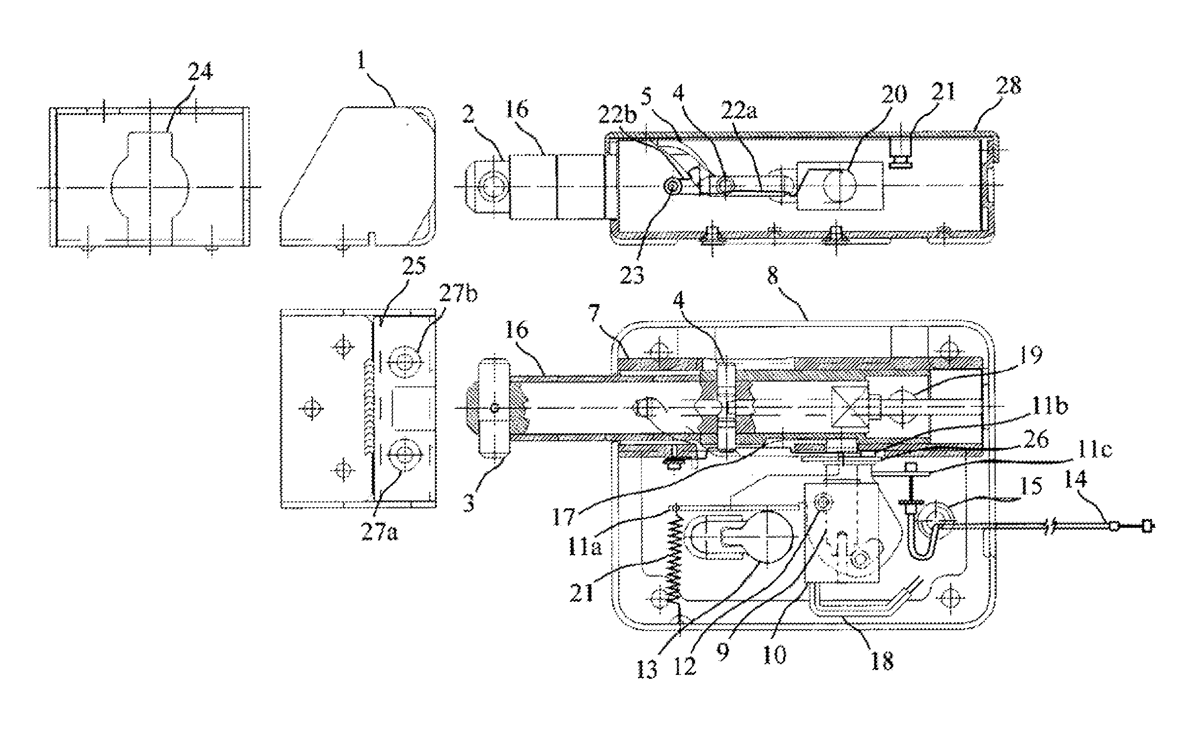
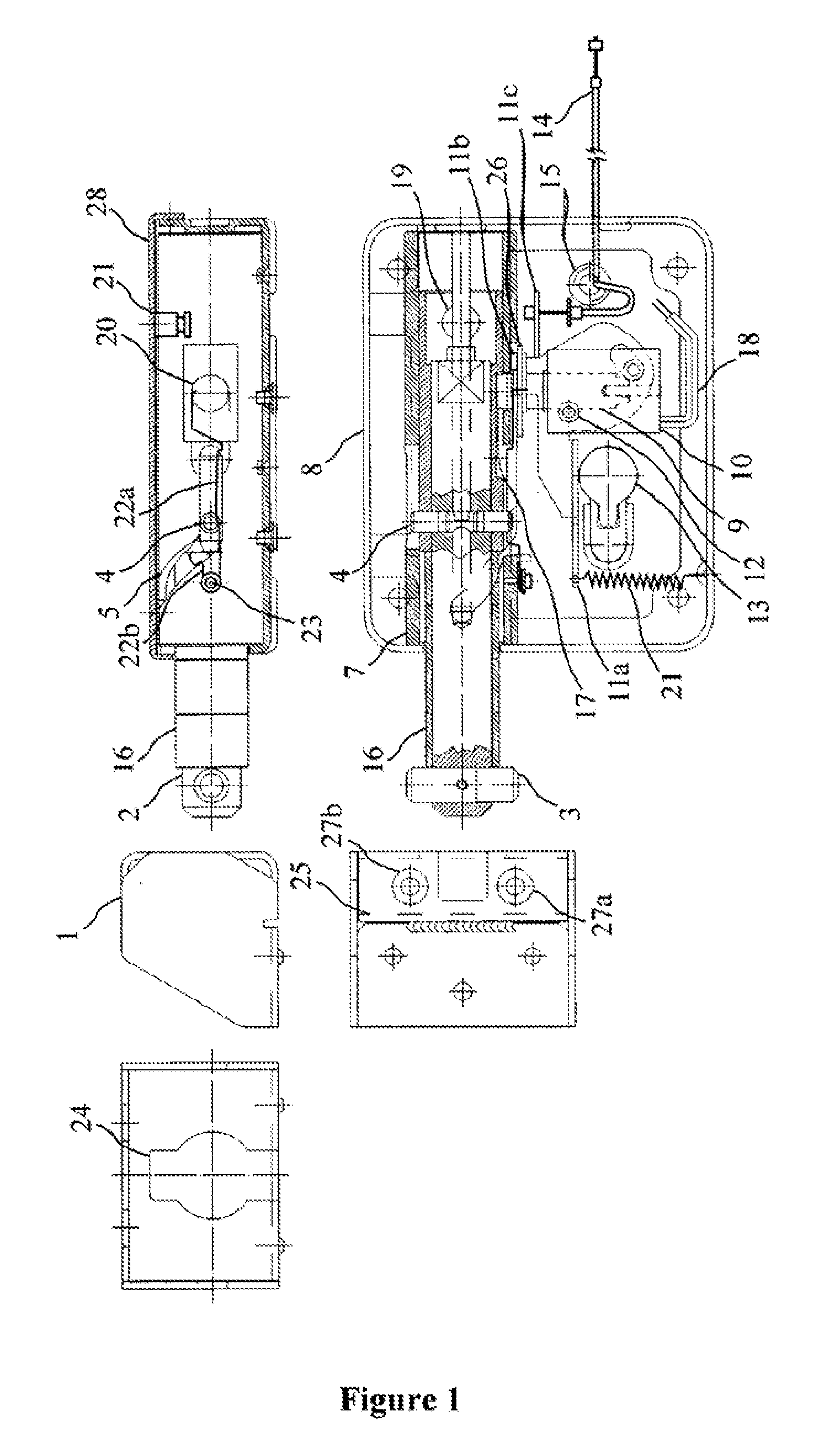
[0026]In Figure is presented a preferred embodiment of the device object of the present invention.

[0027]The device comprises one piston (2) that is protruding in the gap between the sliding gate and its frame, and is characterized by at least one laterally protruding tooth (3) close to its free edge the will be named head of the harpoon in the description that follows.

[0028]When the gate is closi...


PUM


Abstract

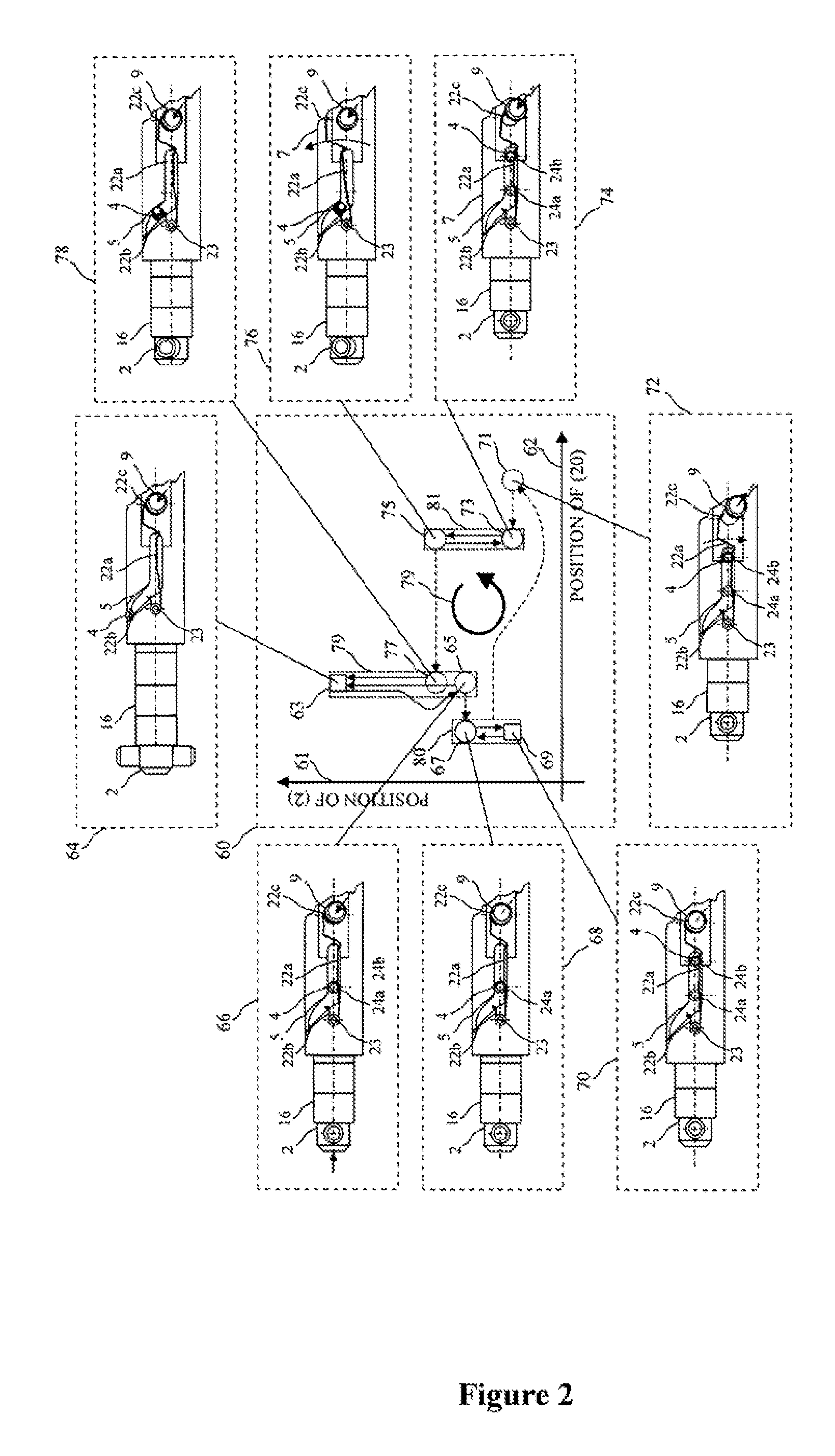
A lock device for sliding gates has a harpoon-type bolt element whose head enters a cavity of a keeper from a shaped hole, and is pushed inside a sleeve by a roto-translation that is controlled by a cam and tappet coupling until the system is locked Reverse motion is prevented by engagement between the anchor of a solenoid and an elongated cavity on the surface of the bolt shaft, however allowing the bolt to tolerate axial displacements from thermal changes or settlements. An unlock control logic allows release of the engagement via a European profile lock cylinder, a mechanical control remotely operated through a Bowden wire, or an electrically controlled solenoid. The control logic ensures the system operation follows the correct direction of motion of a cyclic state machine, to provide proper synchronization with the operation of the gate automation.

Description

TECHNICAL FIELD OF THE INVENTION[0001]The present invention relates to a rotating harpoon bolt type lock device for sliding-type gates and to a control method for the same device that is intended to ensure its proper operation when the device is installed on an automatically-operated gate.PREVIOUS STATE OF THE ART[0002]Several different types of lock devices for sliding-type doors are known. Patents DE 102008027081A1 (Dziurdzia; Koenkler), GB2457990A (Bradbury), JP2009174174A (Nakagawa; Takeda) and JP2010121437A (Hamawaki) disclose lock device mechanisms having at least one bolt that is moved along an axis normal to the direction of motion of the sliding door.[0003]Patents GB2197381A (Wong Kwan-Yu), GB868366 (Goh Hiow), KR100773299B 1, KR 100891104B1 (fang Kong Ik), KR200440287Y 1, KR200443554Y1, KR20090009277U, KR20090081802A (Kim Yong Bum) and US2009267361A1 (Alber) disclose lock device mechanisms having one or more hook-type bolts that rotates around an axis normal to the directi...

Claims


Application Information

Patent Timeline
Patent Type & Authority Applications(United States)
IPC IPC(8): E05B47/02
CPCE05B47/00E05B53/005E05B47/023E05B65/0007E05C5/02E05B63/125Y10T292/1082
Inventor BASTIANINI, FILIPPO
Owner VIRO INNOCENTI
Learn More