Magneto-impedance sensor element and method for producing the same

Active Publication Date: 2013-07-18
AICHI STEEL
View PDF2 Cites 21 Cited by
  • Summary
  • Abstract
  • Description
  • Claims
  • Application Information

AI Technical Summary

Benefits of technology

[0015]Effects of the first invention will be explained. According to the method for producing the magneto-impedance sensor element according to the present invention, a plurality of magneto-sensitive bodies are formed by fixing the amorphous wire on the substrate, and then cutting it.
[0016]Thus, an exact position of each magneto-sensitive body to be connected is already decided at the time when the wire is fixed on the substrate, and then by only electrically connecting them, all of the magneto-sensitive bodies can easily be arranged in the same direction, and the MI sensor element in a parallel state can be produced. The production, therefore, can be made considerably more efficient, compared to a case in which each MI sensor element to be connected is separately prepared, each MI sensor is fixed, and then connection is further performed between wire ends and the detecting coils with an electrode pattern or wire bonding. In addition, there is no variation at all in the direction of magnetic field to be measured among the magneto-sensitive bodies, which results in the measuring accuracy of magnetism being able to be increased. In addition, a plurality of magneto-sensitive bodies can be formed by using adjacent parts to each other in one amorphous wire. Thus, the properties of a plurality of magneto-sensitive bodies in one MI sensor element can be made almost the same. This can provide an effect in which sensitivity almost the same as the theoretical value can be obtained.
[0017]According to the present invention, after one amorphous wire is fixed on the substrate, the wire is cut. The length of the cut parts can be made remarkably

Problems solved by technology

Such a production is very complicated, and has a problem in which efficient production is difficult.
These structures have a three-dimensionally complicated electr

Method used


Image

  • Magneto-impedance sensor element and method for producing the same
  • Magneto-impedance sensor element and method for producing the same
  • Magneto-impedance sensor element and method for producing the same

Examples


Example

Example 1

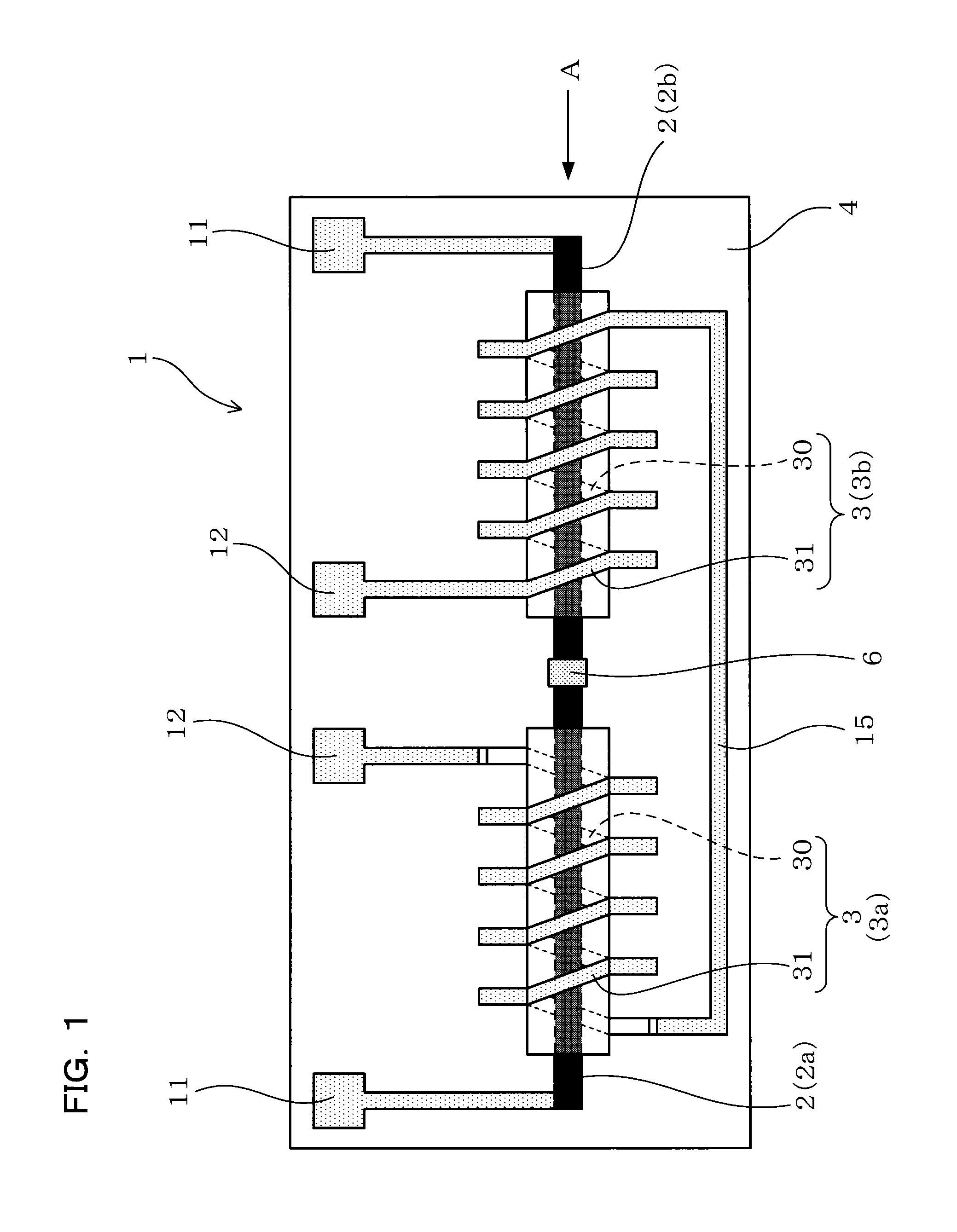
[0048]Magneto-impedance sensor elements according to Example of the present invention will be explained using FIGS. 1 to 11. As shown in FIGS. 1 and 2, an MI sensor element 1 of the present Example includes a substrate 4 formed of a non-magnetic material, a plurality of magneto-sensitive bodies 2 (2a and 2b), and a plurality of detecting coils 3 (3a and 3b).

[0049]The magneto-sensitive body 2 is formed of an amorphous material, and is fixed on the substrate 4. The plurality of magneto-sensitive bodies 2 are electrically connected to each other.

[0050]Also, the detecting coils 3 are formed by wounding around each magneto-sensitive body 2, and are electrically connected to each other.

[0051]The MI sensor element 1 is configured so that a voltage corresponding to a magnetic field strength acting on the magneto-sensitive body 2 is output from the detecting coil 3 by flowing a pulse current or a high-frequency current to the magneto-sensitive body 2.

[0052]The plurality of magneto-s...

Example

Example 2

[0084]The present Example is an example in which the number of magneto-sensitive bodies 21 is changed. As shown in FIG. 12, an MI sensor element 1 in the present Example has a magneto-sensitive body group 21 (21a) including a plurality of magneto-sensitive bodies 2, which are formed by cutting one amorphous wire 20 and are positioned in parallel to an axis line direction. The MI sensor element 1 also has the magneto-sensitive body group 21 (21b) formed by cutting the amorphous wire 20, which is different from the amorphous wire 20 used for forming the magneto-sensitive body group 21a. These groups 21a and 21b of the plurality of magneto-sensitive bodies are positioned adjacent to each other in a radial direction X. One detecting coil 3 is wound around the plurality of magneto-sensitive bodies 2, which are adjacent to each other in the radial direction X.

[0085]One detecting coil 3a is connected to other detecting coil 3b in series through a coil junction 15.

[0086]Other compo...

Example

Example 3

[0089]The present Example is an example in which the number and the position of magneto-sensitive bodies 21 are changed. The MI sensor element 1 in the present Example has a magneto-sensitive body group 21 (21a) including a plurality of magneto-sensitive bodies 2, which are formed by cutting one amorphous wire 20 and are positioned in parallel to an axis line direction. The MI sensor element also has a magneto-sensitive body group 21 (21b) formed by cutting the amorphous wire 20, which is different from the amorphous wire 20 used for forming the magneto-sensitive body group 21a. These groups 21a and 21b of the plurality of magneto-sensitive bodies are positioned adjacent to each other in a radial direction X. A detecting coil 3 is wound around each magneto-sensitive body 2. The plurality of detecting coils 3 are connected to each other in series through the coil junctions 15.

[0090]Other components are the same as in Example 1.

[0091]Effects in the present Example will be exp...


PUM

PropertyMeasurementUnit
Strengthaaaaaaaaaa
Sensitivityaaaaaaaaaa
Electric impedanceaaaaaaaaaa

Abstract

An MI sensor element 1 includes a substrate 4 formed of a non-magnetic material, a plurality of magneto-sensitive bodies 2, and a plurality of detecting coils 3. The plurality of magneto-sensitive bodies 2 are formed of an amorphous material, and are fixed on the substrate 4, and are electrically connected to each other. The detecting coils 3 are wound around each of the magneto-sensitive bodies 2, and are electrically connected to each other. The MI sensor element 1 outputs a voltage corresponding to a magnetic field strength acting on the magneto-sensitive bodies 2 from the detecting coil 3 by flowing a pulse current or a high-frequency current to the magneto-sensitive body 2. The plurality of magneto-sensitive bodies 2 are formed by fixing one amorphous wire 20 on the substrate 4, and then cutting the wire.

Description

TECHNICAL FIELD[0001]The present invention relates to a magneto-impedance sensor element having a magneto-sensitive body formed from an amorphous material, and a method for producing the same.BACKGROUND ART[0002]As a sensor element used in a magnetometric sensor, and the like, a magneto-impedance sensor element, which uses a magneto-sensitive body capable of changing its properties depending on an external magnetic field (hereinafter may be sometimes referred to as “MI sensor element”), are known (see Patent Documents 1 and 2 below).[0003]As shown in FIG. 14, an MI sensor element 91 contains a substrate 94 formed of a non-magnetic material, a magneto-sensitive body 92 which is fixed on the substrate 94 and is formed of the amorphous material, and a detecting coil 93 which is wound around the magneto-sensitive body 92 through an insulator 95.[0004]When a pulse current or a high-frequency current is made to flow into the magneto-sensitive body 92, a voltage corresponding to a magnetic...

Claims


Application Information

Patent Timeline
IPC IPC(8): G01R33/06G01R3/00
CPCG01R33/063G01R3/00Y10T29/49021
Inventor HONKURA, YOSHINOBUYAMAMOTO, MICHIHARUHAMADA, NORIHIKO
Owner AICHI STEEL
Why Eureka
Try Eureka