Battery system

Inactive Publication Date: 2013-07-18
SANYO ELECTRIC CO LTD
View PDF2 Cites 1 Cited by
  • Summary
  • Abstract
  • Description
  • Claims
  • Application Information

AI Technical Summary

Benefits of technology

[0035]According to the thus-constructed battery system, since the welding ring can be temporarily held at the position where the outer periphery of the welding ring is brought in contact with the surface of the metal plate when the terminal rod is inserted into the welding ring, the terminal rod can be simply, easily and smoothly inserted into the welding ring so that the outer periphery of the welding ring is brought in contact with the surface of the metal plate. The reason to allow the terminal rod to smoothly receive the welding ring is that the elastic part can

Problems solved by technology

However, if the nut is screwed at high torque, a large force will be exerted on the terminal rod.
Such a large force exerted on the terminal rod may cause the failure of a part that couples the terminal rod to the exterior container of a battery.
If the nut is screwed at low torque in order to prevent the failure of the terminal rod, this may cause a problem that the metal plate cannot be stably electrically connected to the terminal rod

Method used


Image

  • Battery system
  • Battery system
  • Battery system

Examples


Example

[0054]The following description will describe embodiments according to the present invention with reference to the drawings. It should be appreciated, however, that the embodiments described below are illustrations of a battery system to give a concrete form to technical ideas of the invention, and a battery system of the invention is not specifically limited to description below. In this specification, reference numerals corresponding to components illustrated in the embodiments are added in “Claims” and “SUMMARY OF THE INVENTION” to aid understanding of claims. However, it should be appreciated that the members shown in claims attached hereto are not specifically limited to members in the embodiments.

[0055]A battery system can be mainly installed on an electric vehicle such as hybrid car and electric car, and is used as a power supply which supplies electric power to an electric motor of the electric vehicle whereby driving the electric vehicle.

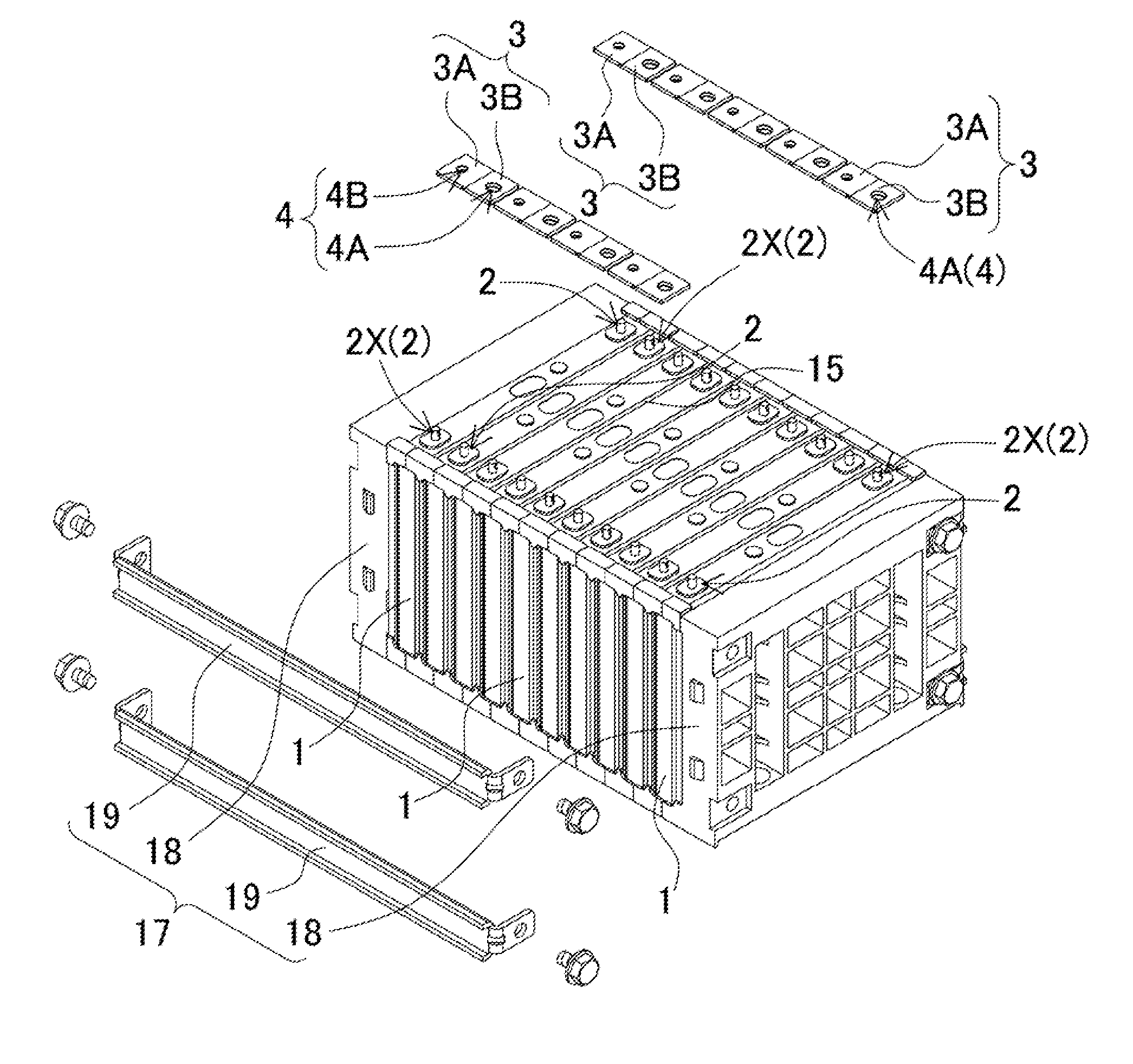
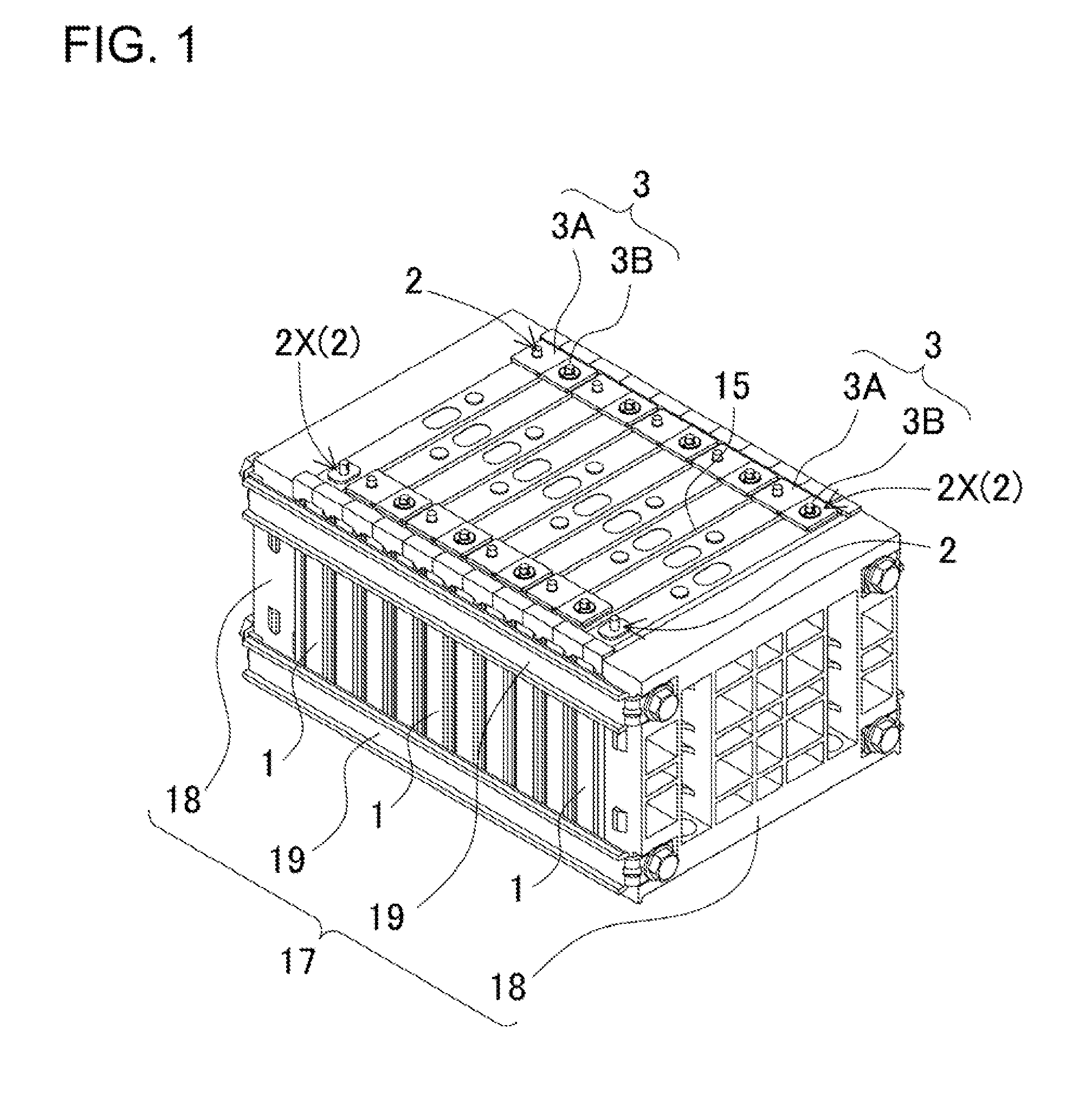
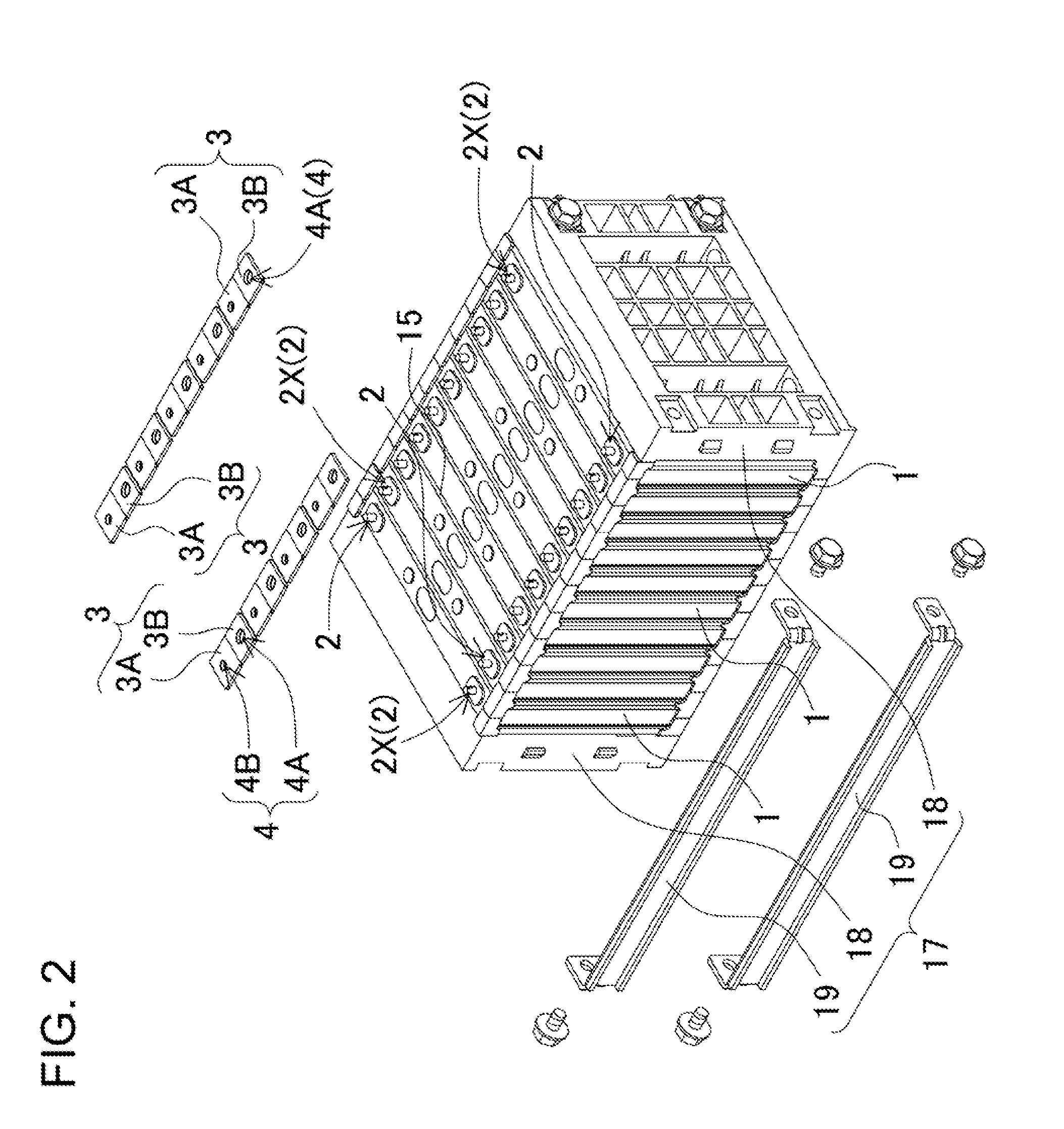
[0056]In a battery system shown in F...


PUM


Abstract

A battery system includes battery cells, metal plates, and welding rings. The battery cell includes terminal rods. The battery cells are connected to each other through the metal plates. The welding rings are arranged on the metal plates, and have insertion holes into which the terminal rods are inserted. The surface of the insertion hole is welded to the terminal rod. The periphery of the welding ring is welded to the metal plate after the terminal rod is inserted into the insertion hole. The terminal rods are electrically connected to the metal plates through the welding rings. The terminal rod and/or the welding ring includes a stopper that temporarily holds the welding ring at a predetermined position with the welding ring being connected to the terminal rod. The temporarily held position is the position where the periphery of the welding ring is in contact with the metal plate.

Description

BACKGROUND OF THE INVENTION[0001]1. Technical Field[0002]The present invention relates to a battery system including a plurality of battery cells that are connected to each other through metal plates, and in particular to a battery system suitable for power supply for a motor that can drive electric vehicles such as hybrid car, fuel-cell car, electric car and electric motorcycle.[0003]2. Description of the Related Art[0004]In the case where a battery system includes a number of battery cells that are connected to each other in series, the output voltage of the battery system can be high. On the other hand, in the case where a battery system includes a number of battery cells that are connected to each other in parallel, the battery system can be charged / discharged at a large current rate. In large current, high output battery systems that can be used as power supply for an electric motor for driving a car, a plurality of battery cells are connected to each other in series so that th...

Claims


Application Information

Patent Timeline
IPC IPC(8): H01M2/20H01M50/209H01M50/503H01M50/516H01M50/522H01M50/55H01M50/553
CPCH01M2/1077H01M2/206H01M2/305H01M10/34H01M2/202H01M10/5016H01M10/5032H01M10/5055H01M10/5004H01M10/625H01M10/647H01M10/6555H01M10/613Y02E60/10H01M50/522H01M50/209H01M50/516H01M50/55H01M50/553H01M50/503
Inventor ASAI, YASUHIRO
Owner SANYO ELECTRIC CO LTD
Why Eureka
Try Eureka