
Control device for automatic transmission

a control device and automatic transmission technology, applied in road transportation, instruments, transportation and packaging, etc., can solve the problems of increased fuel consumption, increased driving force, and increased stepped amount of accelerator pedal by the driver, so as to reduce the amount of fuel consumption, and reduce the effect of fuel consumption

Active Publication Date: 2013-07-18
HONDA MOTOR CO LTD
View PDF2 Cites 55 Cited by
  • Summary
  • Abstract
  • Description
  • Claims
  • Application Information

AI Technical Summary

Benefits of technology

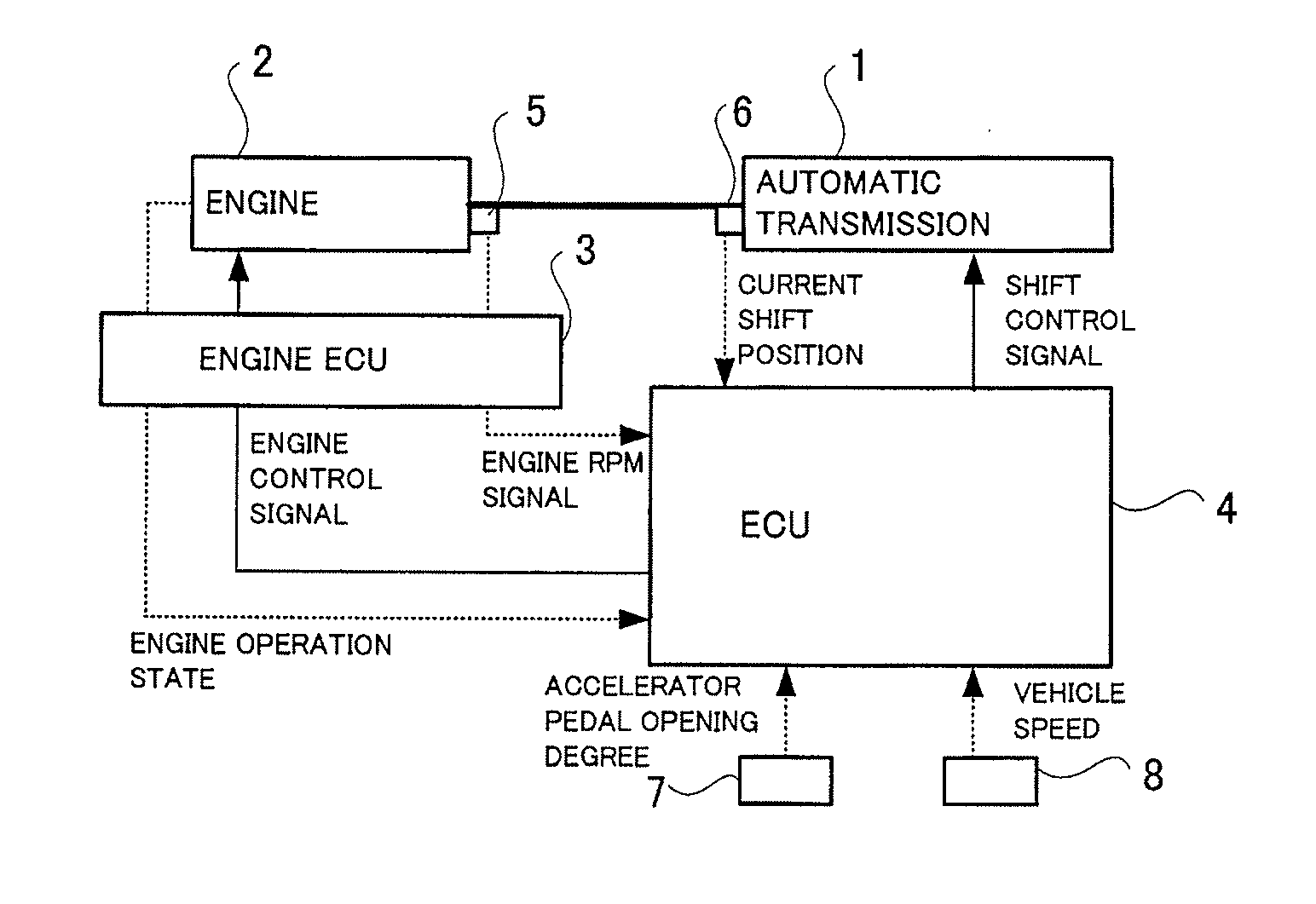
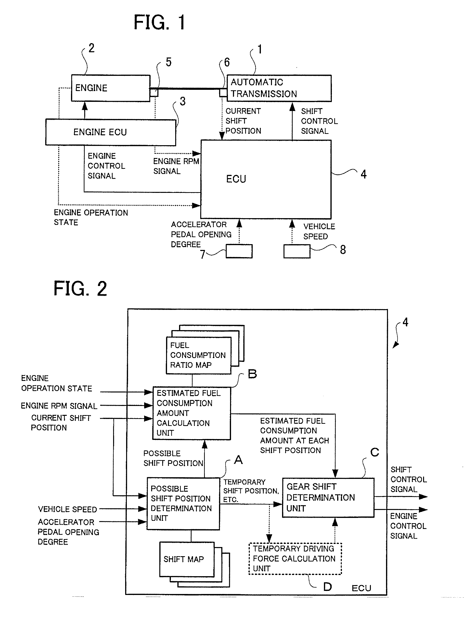
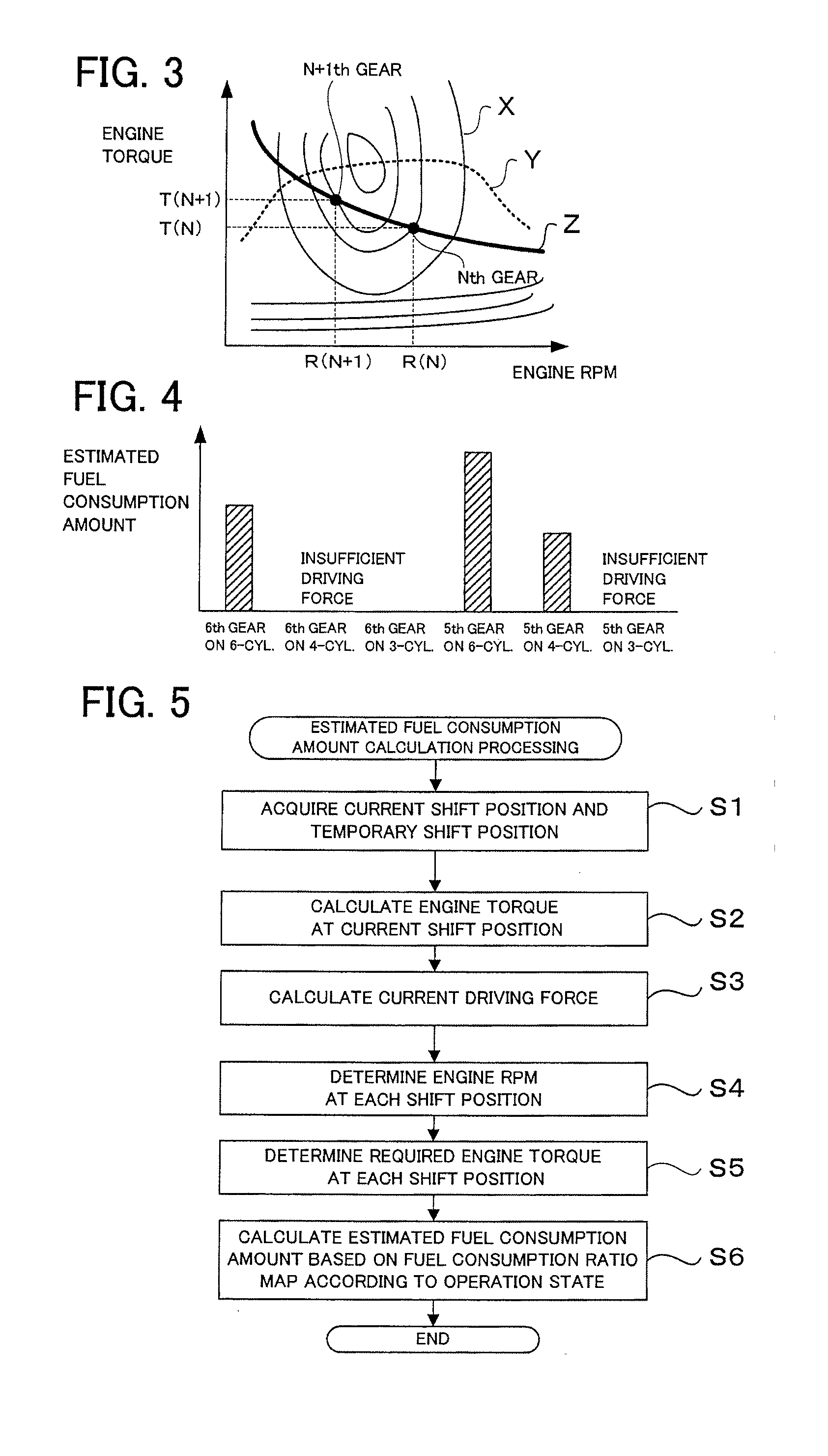
The present invention provides a control device for an automatic transmission that can reduce fuel consumption by both shift-up and cylinder deactivation operations of a variable cylinder engine. The device calculates the fuel consumption amount required to maintain the current traveling state of the vehicle for each gear and shift position, and allows an automatic shift control to shift to the gear after a possible shift-up only when the fuel consumption amount is smaller, thus reducing fuel consumption without degrading traveling performance. Additionally, the device takes into account the engine operation state of the variable cylinder engine to further reduce fuel consumption. The invention allows for efficient shift control and reduced fuel consumption, even in vehicles equipped with a variable cylinder engine.

Problems solved by technology

However, when the shift-up control is made quickly while a vehicle travels on an uphill road, a driving force may be insufficient and a stepped amount of an accelerator pedal by a driver may suddenly increase, and in the worst case, for example, another shift-down may cause an increase in fuel consumption.
However, in the case of a vehicle equipped with the variable cylinder engine, there is a possibility that any cylinder deactivation operation of the engine cannot be operated due to the performance of the shift-up control.

Method used


Image

  • Control device for automatic transmission
  • Control device for automatic transmission
  • Control device for automatic transmission

Examples


second embodiment

[0054]FIG. 8 is a flow chart illustrating an example of the gear shift determination processing according to the In step S21, it is determined whether the current shift position and the possible shift position are acquired. When the current shift position and the possible shift position are not acquired (NO in step S21), the shift position determination processing repeats the processing of step S21. When the current shift position and the possible shift position are acquired (YES in step S21), the estimated driving force calculated by the estimated driving force calculation unit D is acquired (step S22). Next, in step S23, the required driving force is calculated based on the current driving force. Next, in step 24, it is determined whether the estimated driving force is larger more than a predetermined value than the required driving force by comparing the estimated driving force with the required driving force. If it is determined that the estimated driving force is not larger mo...

third embodiment

[0056]In the third embodiment, the gear shift determination unit C compares the estimated driving force calculated by the estimated driving force calculation unit D with the required driving force according to the minimum target engine torque required to maintain the current traveling state of the vehicle, and when the estimated driving force is larger more than the predetermined value than the required driving force, outputs the shift control signal for performing the shift-up control to the possible shift position. However, in this embodiment, the gear shift determination unit C specifies an operation state having the smallest fuel consumption amount among the calculated estimated fuel consumption amounts acquired from the estimated fuel consumption amount calculation unit B and outputs the specified operation state as the engine control signal at the same time of outputting the shift control signal. By doing so, the operation state of the engine 2 is maintained in a cylinder deac...


PUM


Abstract

For each engine operation state to which a variable cylinder engine can be switched, a fuel consumption amount to be consumed to generate a driving force required to maintain a current traveling state of a vehicle for each of a current gear and a new gear after a possible shift-up is calculated. An automatic shift control of shifting up to the new gear is performed in a condition that a calculated fuel consumption amount of the new gear after the possible shift-up is smaller than a calculated fuel consumption amount of the current gear. In this way, the fuel consumption amount can be optimally reduced and the shift control can be performed without degrading the traveling performance, even in the vehicle equipped with the variable cylinder engine.

Description

BACKGROUND[0001]The present invention relates to a control device for an automatic transmission in a vehicle capable of automatically shifting a gear of the automatic transmission to a gear at which the vehicle can travel at the lowest fuel consumption. More particularly, the present invention relates to a technology of performing a shift control for reducing a fuel consumption amount without degrading traveling performance, in an automatic transmission in a vehicle equipped with a variable cylinder engine that can be operated in a cylinder deactivation state.[0002]As a control device for an automatic transmission in a vehicle, there is a control device in which a plurality of types of shift maps that define shift characteristics are prepared, any one of the shift maps is selected based on a determination of whether a vehicle is traveling on an uphill road or a downhill road, a gear (also referred to as a shift position) is determined according to a traveling speed (vehicle speed) o...

Claims


Application Information

Patent Timeline
IPC IPC(8): B60W10/11
CPCB60W10/11B60W10/06B60W30/1882B60Y2300/435F16H2061/0015F16H2061/022Y02T10/76F16H2059/6815F16H61/0213F16H2061/0216Y02T10/60
Inventor SAITO, HIROSHIISHIKAWA, YUTAKA
Owner HONDA MOTOR CO LTD
Learn More