
Integrated circuit design method and system

a technology of integrated circuits and circuits, applied in the field of integrated circuit design, can solve the problems of increasing resistance or failure, increasing current density, etc., and achieve the effect of avoiding/minimizing electromigration failures

Active Publication Date: 2013-07-18
MARVELL ASIA PTE LTD
View PDF4 Cites 7 Cited by
  • Summary
  • Abstract
  • Description
  • Claims
  • Application Information

AI Technical Summary

Benefits of technology

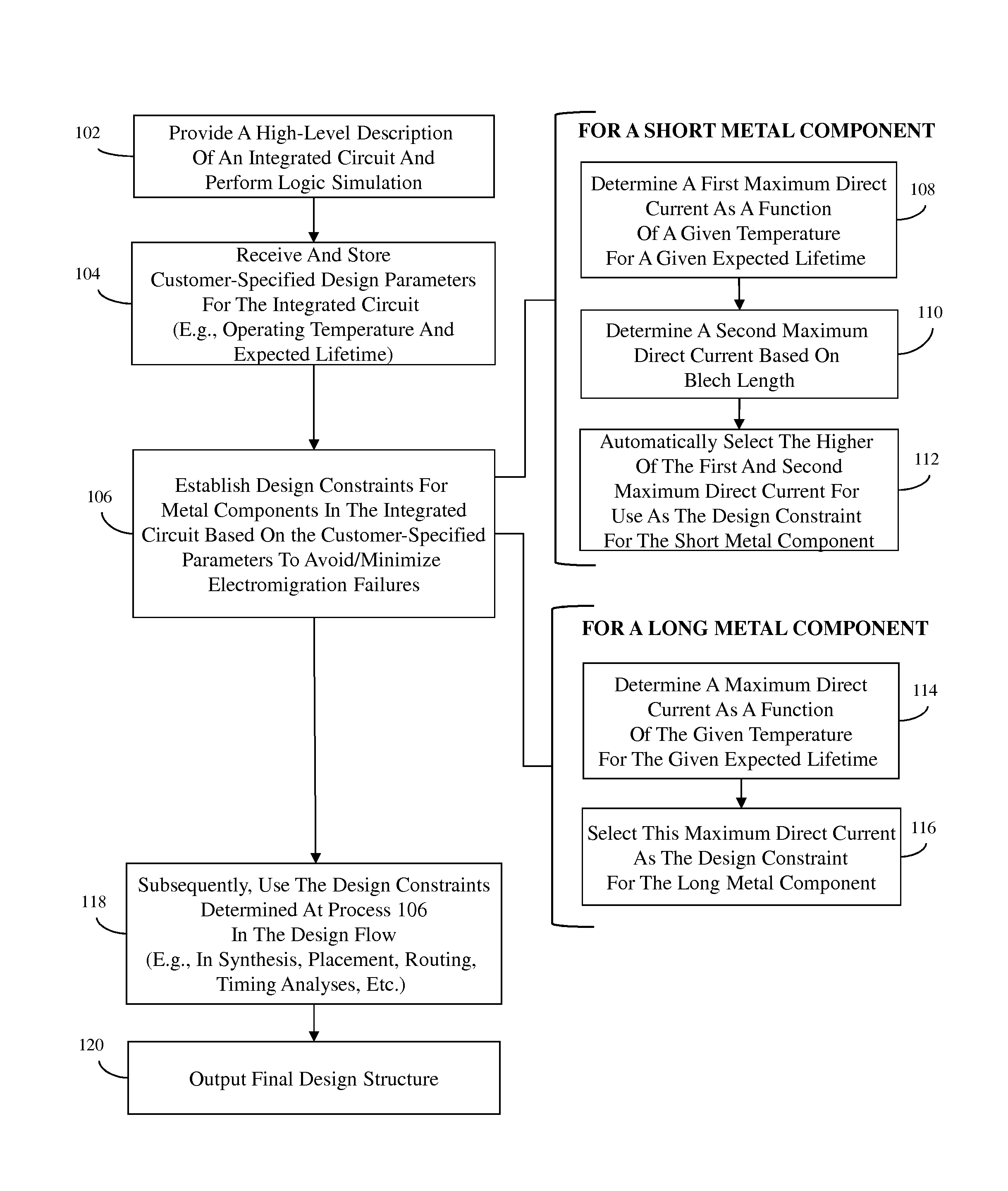
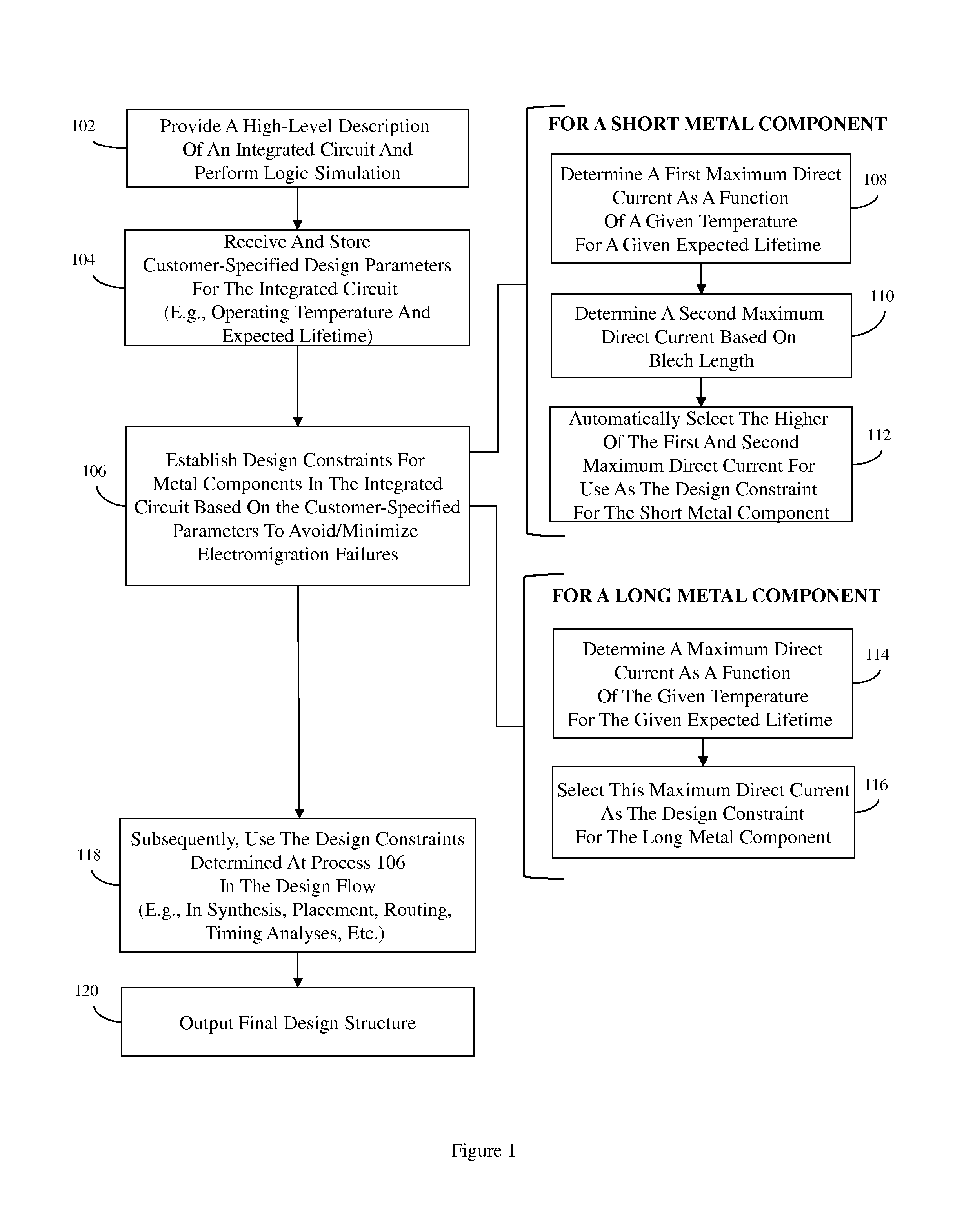
The patent text describes a method and system for designing integrated circuits that use maximum direct currents for metal components to avoid and minimize electromigration failures. The method determines the maximum direct current for a metal component based on its length and the expected lifetime of the circuit. By using these maximum direct currents as design constraints, the system can automatically select the more stringent of the two constraints, reducing the risk of electromigration failures. The system includes a design constraint calculator that determines the maximum direct currents for short and long metal components and uses them as design constraints in the design flow. The technical effect of this method and system is to improve the reliability and performance of integrated circuits by reducing the risk of electromigration failures.

Problems solved by technology

Over time this metal atom displacement can cause cracks (i.e., voids, opens, etc.) in the metal component and can result in either increased resistance or failure.
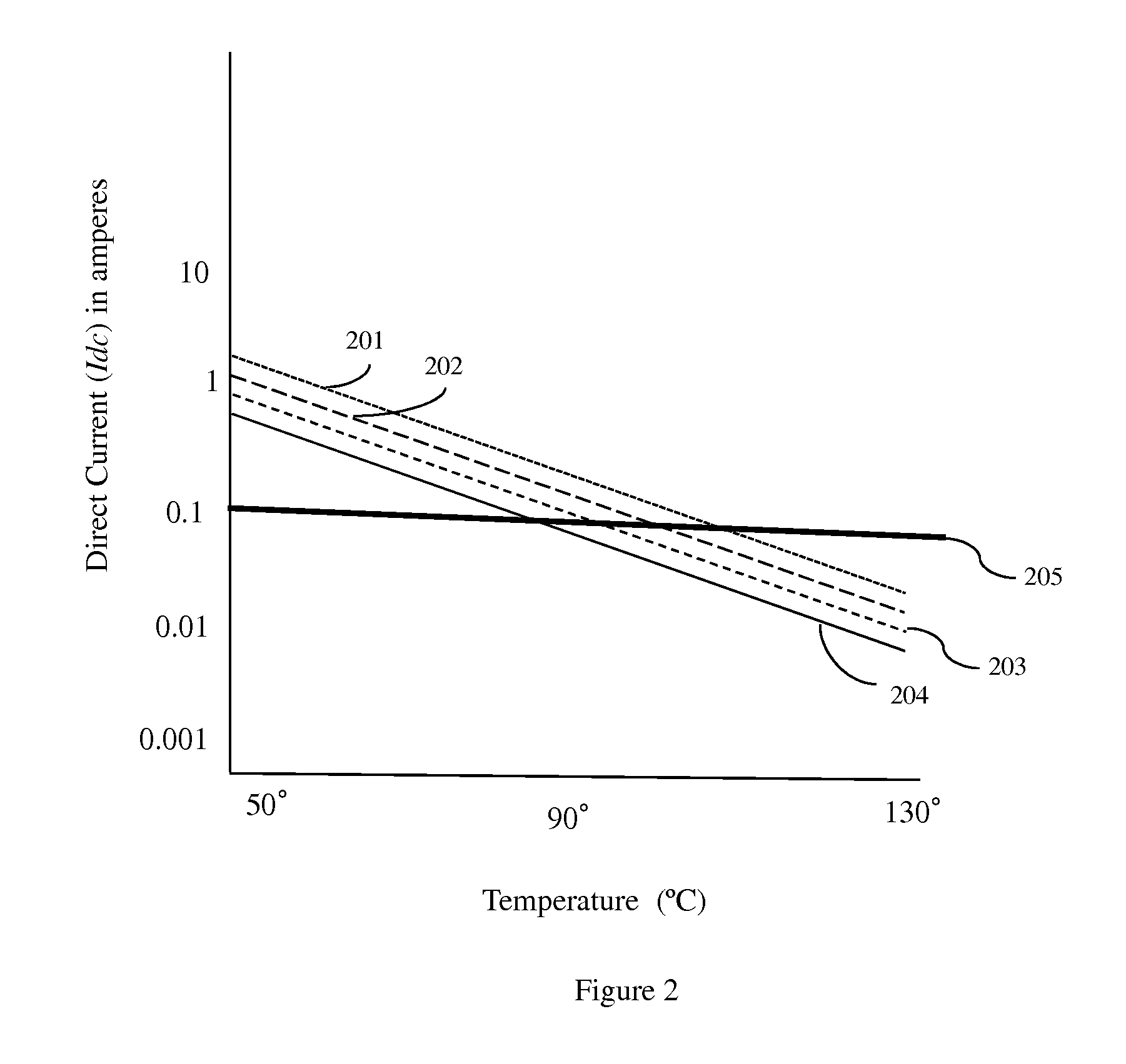
Consequently, as integrated circuit feature sizes decrease resulting in a corresponding increase in current density and as integrated circuit operating temperatures and expected lifetimes (i.e., power-on-hours (POH)) also increase at each new technology node, failures due to electromigration have become a major concern for integrated circuit designers.

Method used


Image

  • Integrated circuit design method and system
  • Integrated circuit design method and system
  • Integrated circuit design method and system

Examples


Embodiment Construction

[0016]As mentioned above, there are various failure mechanisms, which are associated with different classes of devices and / or with metal components of an integrated circuit (e.g., interconnects, wires, pads, vias, etc.) and which can cause the performance of integrated circuits to degrade over time. One such failure mechanism is electromigration. Electromigration is a condition in which atoms of a metal component are displaced due to the current passing through that metal component. Over time this metal atom displacement can cause cracks (i.e., voids, opens, etc.) in the metal component and can result in either increased resistance or failure. Since electromigration is caused by the collision between electrons and metal ions as direct current passes through the metal component, it is significant at relatively high direct current densities (i.e., when the ratio of direct current flow to unit area of cross-section is relatively high) and it is accelerated at relatively high temperatur...


PUM


Abstract

Disclosed is an integrated circuit design method that determines maximum direct currents for metal components and uses them as design constraints in the design flow in order to avoid / minimize electromigration failures. Short and long metal components are treated differently for purposes of establishing the design constraints. For a short metal component, the maximum direct current as a function of a given temperature for a given expected lifetime of the integrated circuit is determined, another maximum direct current is determined based on the Blech length, and the higher of these two is selected and used as the design constraint for that short metal component. For a long metal component, only the maximum direct current as a function of the given temperature for the given expected lifetime is determined and used as the design constraint. Also disclosed herein are associated system and program storage device embodiments for designing an integrated circuit.

Description

BACKGROUND[0001]1. Field of the Invention[0002]The embodiments disclosed herein relate to integrated circuit design and, more particularly, to a method, system and program storage device that, based on customer-specified design parameters for an integrated circuit, including operating temperature and expected life-time, automatically selects between two different electromigration violation thresholds for a short metal component and, subsequently, uses the selected electromigration violation threshold as a design constraint for the metal component during a design flow.[0003]2. Description of the Related Art[0004]Those skilled in the art will recognize that there are various failure mechanisms, which are associated with different classes of devices and / or with metal components of an integrated circuit (e.g., nets, local-interconnects, pads, vias, etc.) and which can cause the performance of integrated circuit to degrade over time. One such failure mechanism is electromigration. Electr...

Claims


Application Information

Patent Timeline
Patent Type & Authority Applications(United States)
IPC IPC(8): G06F17/50
CPCG06F17/5068G06F2217/78G06F2217/76G06F30/39G06F2119/04G06F2119/06
Inventor BARWIN, JOHN E.JOSHI, AMOL A.LI, BAOZHENOUELLETTE, MICHAEL R.
Owner MARVELL ASIA PTE LTD
Learn More