Apparatus for collection of garden waste

a technology for collecting garden waste and accessories, applied in the field of accessories for collecting garden waste, can solve the problems of user clothing, increased turbulence and energy loss in the air flow, and user's dirtying or wetting, and achieve the effect of preventing the insertion of a human finger and minimizing the resistan

Active Publication Date: 2013-07-25
BLACK & DECKER INC
View PDF6 Cites 36 Cited by
  • Summary
  • Abstract
  • Description
  • Claims
  • Application Information

AI Technical Summary

Benefits of technology

[0015]The present invention avoids the use of a porous collection bag. Instead of removing garden waste by filtration, which progressively clogs the collection bag's pores and inhibits escape of air flow, the apparatus of the present invention removes the garden waste by cyclonic separation. Volumetric flow rate of air flowing through the apparatus remains generally constant as separated material accumulates in the cyclonic separation arrangement. Thus, an attraction of cyclonic separation is a consistent ability to pick up garden waste. Cleaned air flow can be directed to open atmosphere from the cyclonic separating apparatus rather than permeating the wall of a porous collection bag and risk dirtying, or wetting, the user's clothing. Also, rather than using one toroidal chamber for both enclosing the impeller and for cyclonic separation, the apparatus of the present invention splits these two functions between the volute and the cyclonic separating apparatus. This provides a more slender cyclonic separation arrangement as it need not accommodate its cyclonic separation around an impeller. Dirty air flows tangentially from the impeller and directly out the volute rather than being diverted in an axial direction and increasing turbulence and energy losses in the air flow. Cleaned air is expelled from the cyclonic separating apparatus rather than being recycled via the vacuum tube and diminishing the suction force at the tip of the vacuum tube.
[0029]Preferably, the hand-holdable unit comprises an interlock mechanism for preventing operation of the motor when neither the first attachment nor the second attachment is engaged therewith. This prevents a user from being injured by operation of the impeller when it is exposed. Such an interlock mechanism is described, for example, in European patent publication No. 0 723 759 of Black & Decker Inc. Also to protect users from being injured by operation of the impeller, the air outlet of the volute may comprise an obstruction which allows the passage of mulched garden waste therethrough, but which prevents the insertion of a human finger into the volute sufficiently far to contact the impeller. If required, a similar obstruction may also be provided on the air outlet of the second volute, for example if this air outlet is exposed to a user by detachment of the blowing tube from the second volute. In a preferred embodiment, the air outlet of the volute or the second volute comprises a tube and the obstruction therein comprises one or more vanes formed on the inner surface of said tube and aligned with the longitudinal axis thereof. Such an embodiment has the advantage of preventing the insertion of a human finger into the volute, whilst also minimizing the resistance presented by the obstruction to the passage of air and possibly also garden waste through the air outlet.

Problems solved by technology

Cleaned air flow can be directed to open atmosphere from the cyclonic separating apparatus rather than permeating the wall of a porous collection bag and risk dirtying, or wetting, the user's clothing.
Dirty air flows tangentially from the impeller and directly out the volute rather than being diverted in an axial direction and increasing turbulence and energy losses in the air flow.

Method used


Image

  • Apparatus for collection of garden waste
  • Apparatus for collection of garden waste
  • Apparatus for collection of garden waste

Examples


Embodiment Construction

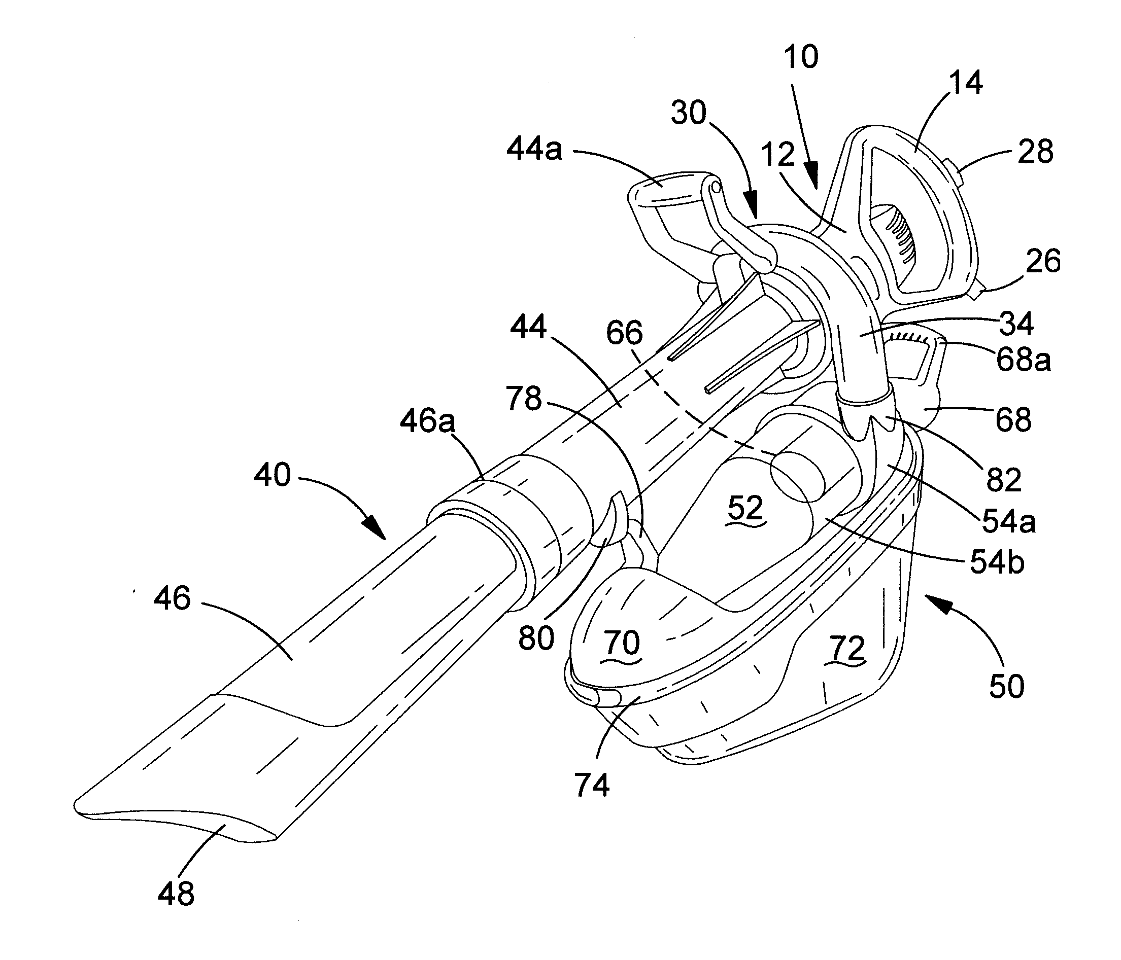
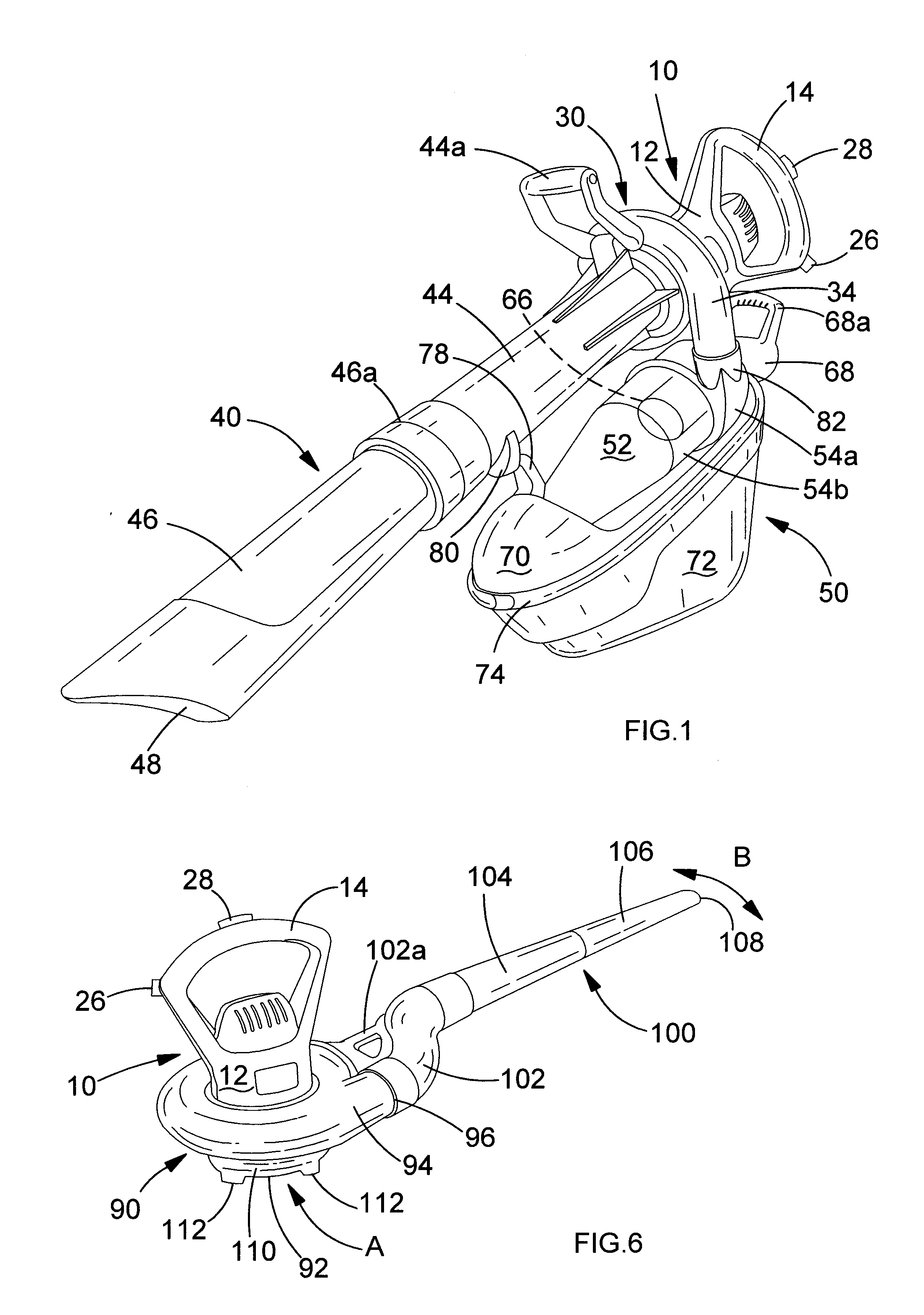
[0040]Referring to FIG. 1, there is shown an apparatus for collection of garden waste according to the present invention. The apparatus comprises a hand-holdable unit 10, a volute 30 attached to the hand-holdable unit, a vacuum tube 40 attached to the volute and a cyclonic separation arrangement 50 mounted below the volute and the vacuum tube.

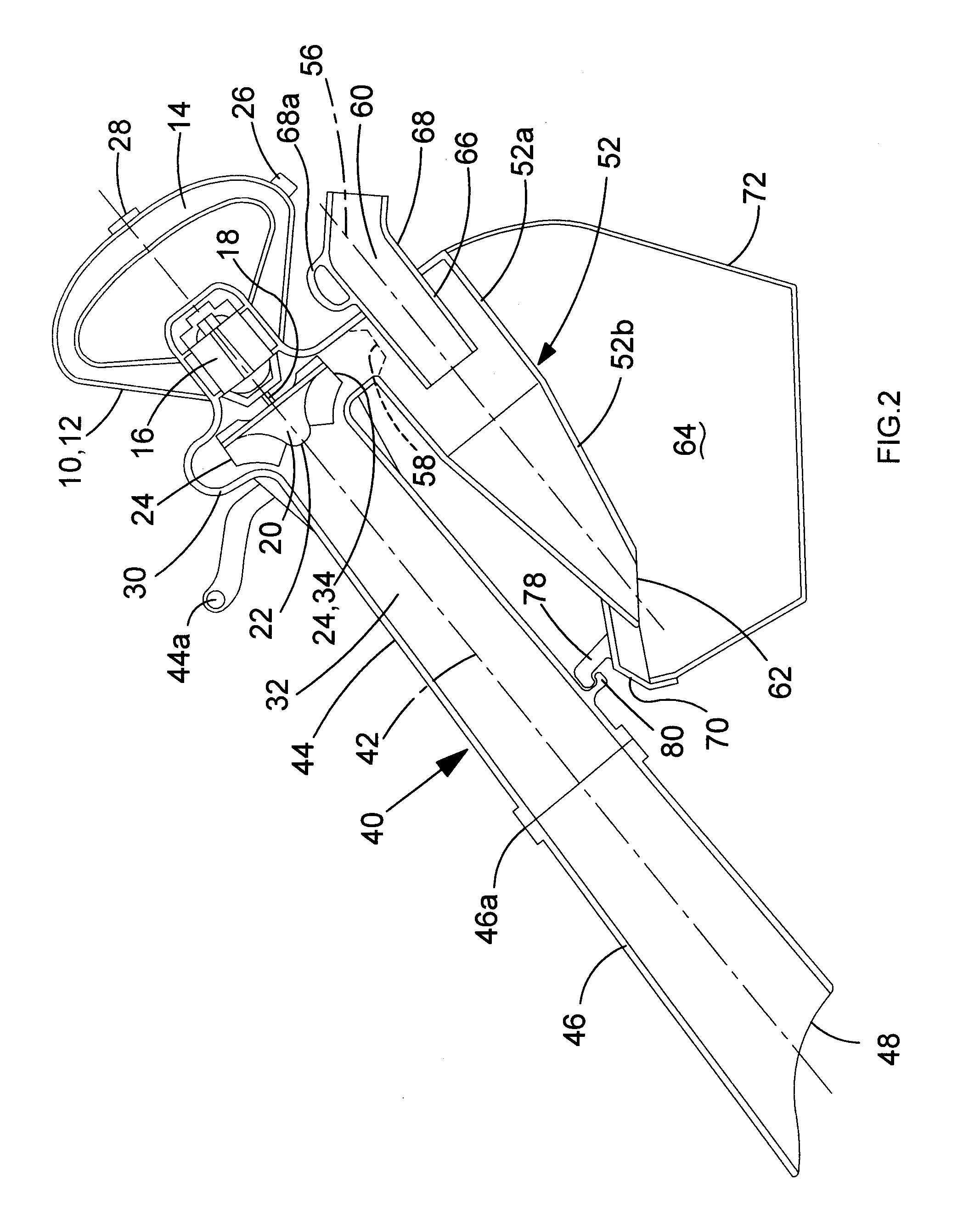
[0041]Referring to FIGS. 1 and 2, the hand-holdable unit 10 comprises a body 12 with a handle 14 for grasping by the user. The body encloses a motor 16 with a drive shaft 18 coupled to a fan 20 for generating air flow. The fan is an impeller 20 with an axial input 22 facing away from the motor and a tangential output 24. The hand-holdable unit further comprises a power inlet 26 for attachment of a cable to supply mains electrical power and an on / off switch 28 for electrically coupling the motor to the mains electrical supply.

[0042]The volute 30 comprises a hollow body with a spiral-shaped interior which encloses the impeller 20 and directs air ...


PUM


Abstract

An apparatus for collection of garden waste wherein the apparatus has a vacuuming mode of operation and a dirty fan operation in the vacuuming mode of operation thereof, the apparatus comprising: a hand-holdable unit comprising a motor with an output shaft coupled to an impeller for generation of air flow; a volute enclosing the impeller for direction of air flow from an axial air inlet of the volute past the impeller to a tangential air outlet of the volute; a vacuum tube for conducting dirty air flow to the air inlet of the volute in the vacuuming mode of operation; and a cyclonic separation arrangement for receiving dirty air flow from the air outlet of the volute and separating garden waste from said dirty air flow in the vacuuming mode of operation. A blowervac comprising the apparatus for collection of garden waste.

Description

CROSS-REFERENCE TO RELATED APPLICATIONS[0001]This application claims priority to European Patent Application No. 12152175.1 filed Jan. 23, 2012. The entire contents of that application are expressly incorporated herein by reference.FIELD OF THE INVENTION[0002]The present invention concerns an apparatus for collection of garden waste used for collecting garden waste such as leaves, grass cuttings and twigs. More particularly, the present invention concerns apparatus for collection of garden waste having a vacuuming mode of operation with a dirty fan. The meaning of the term “dirty fan” will be explained in detail below.BACKGROUND OF THE INVENTION[0003]Apparatus for collection of garden waste for use in the garden are well known. One type of device comprising an apparatus for collection of garden waste is a blower-vacuum device, commonly referred to as a “blowervac”. Blowervacs generally comprise a motor having an output shaft coupled to a fan. The motor is usually either petrol or el...

Claims


Application Information

Patent Timeline
Patent Type & Authority Applications(United States)
IPC IPC(8): A47L5/14A47L5/24
CPCA01G1/125A47L5/24A47L5/14A01G20/47
Inventor WALKER, ANDREW
Owner BLACK & DECKER INC
Why Eureka
Try Eureka