Electrical connector assembly with EMI cover

a technology of electrical connectors and covers, applied in the direction of emi leakage reduction, coupling device details, coupling device connections, etc., can solve the problems of electrical interference with the pluggable module(s) received within the cage or neighboring electrical devices, and the emission of electromagnetic interference (emi) emissions may leak into and/or out of the cag

Active Publication Date: 2013-07-25
TYCO ELECTRONICS LOGISTICS AG (CH)
View PDF27 Cites 16 Cited by
  • Summary
  • Abstract
  • Description
  • Claims
  • Application Information

AI Technical Summary

Problems solved by technology

But, electromagnetic interference (EMI) emissions may leak into and/or out of the cage and electrically inte

Method used


Image

  • Electrical connector assembly with EMI cover
  • Electrical connector assembly with EMI cover
  • Electrical connector assembly with EMI cover

Examples


Embodiment Construction

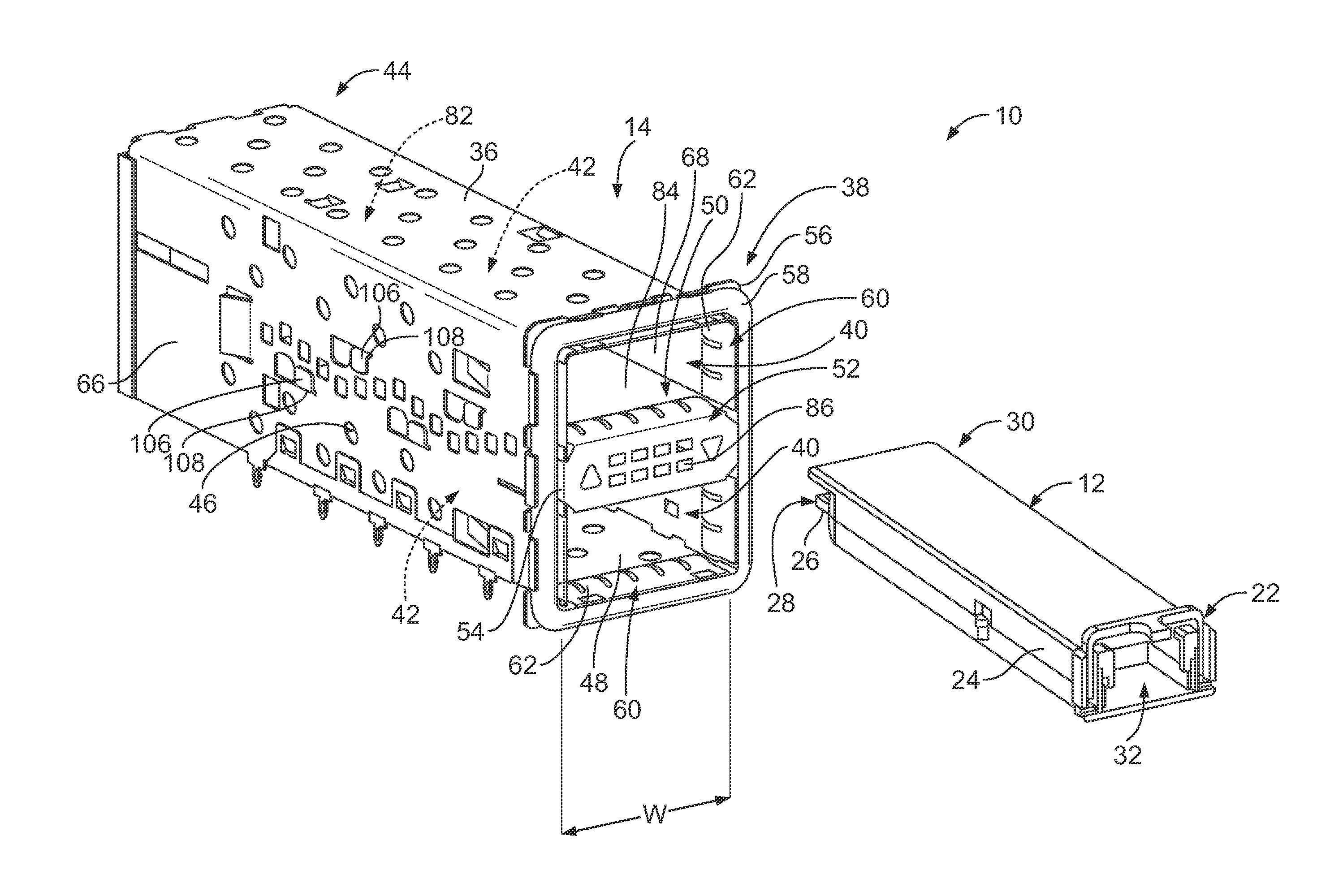
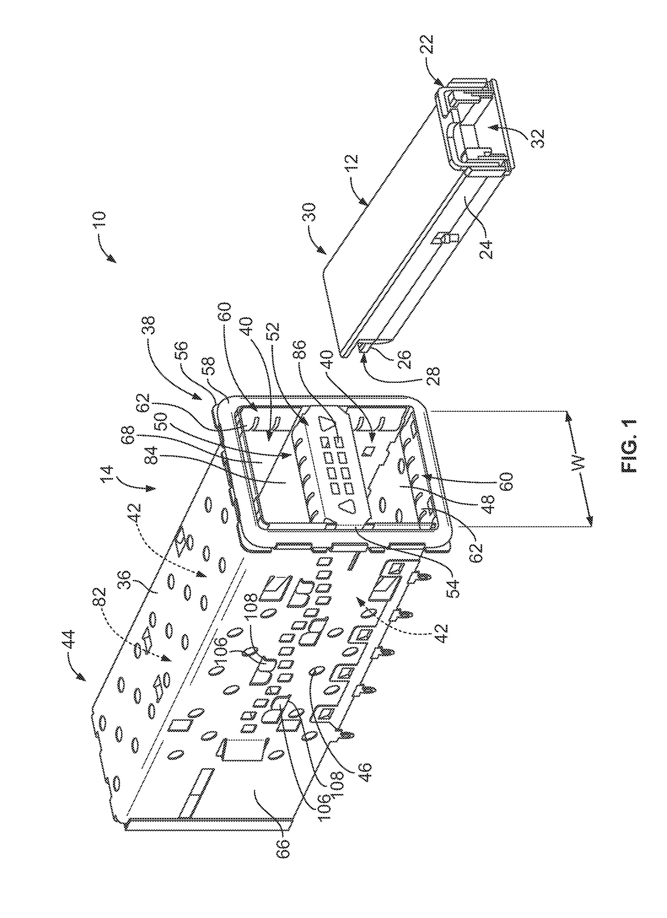
[0013]FIG. 1 is a partially exploded perspective view of an exemplary embodiment of a transceiver assembly 10. In the exemplary embodiment, the transceiver assembly 10 is adapted to address, among other things, conveying data signals at high rates, such as data transmission rates of at least 10 gigabits per second (Gbps), which is required by the SFP+ standard. For example, in some embodiments the transceiver assembly 10 is adapted to convey data signals at a data transmission rate of at least 28 Gbps. Moreover, and for example, in some embodiments the transceiver assembly 10 is adapted to convey data signals at a data transmission rate of between approximately 20 Gbps and approximately 30 Gbps. It is appreciated, however, that the benefits and advantages of the subject matter described and / or illustrated herein may accrue equally to other data transmission rates and across a variety of systems and standards. In other words, the subject matter described and / or illustrated herein is ...


PUM


Abstract

An electrical connector assembly includes a cage having an upper wall, a lower wall, and side walls that extend from the upper wall to the lower wall. The side walls have exterior sides. The cage includes an interior cavity and a divider that extends between the side walls and divides the interior cavity into at least two internal compartments. The cage includes a front end that is open to the internal compartments. The side walls have front edges at the front end. The internal compartments are configured to receive pluggable modules therein through the front end. An electromagnetic interference (EMI) cover is mounted to the divider such that the EMI cover is engaged with and electrically connected to the divider. The EMI cover includes a flap that wraps around the front edge of a corresponding side wall. The flap overlaps and engages the exterior side of the corresponding side wall.

Description

BACKGROUND OF THE INVENTION[0001]The subject matter described and / or illustrated herein relates generally to electrical connector assemblies, and more particularly to electromagnetic interference (EMI) covers for electrical connector assemblies.[0002]Various types of fiber optic and copper based transceiver assemblies that permit communication between host equipment and external devices are known. These transceiver assemblies typically include a pluggable module that is received within a receptacle assembly, which includes a receptacle connector that pluggable connects to the pluggable module. The pluggable modules are constructed according to various standards for size and compatibility, one standard being the Quad Small Form-factor Pluggable (QSFP) module standard. Conventional QSFP modules and receptacle assemblies perform satisfactorily conveying data signals at rates up to 10 gigabits per second (Gbps). Another pluggable module standard, the XFP standard, calls for the transcei...

Claims


Application Information

Patent Timeline
IPC IPC(8): H05K9/00
CPCH05K9/0009H01R13/6583
Inventor WICKES, EVAN CHARLESFOGG, MICHAEL WARRENDUNWOODY, STEVEN DAVIDLONG, RICHARD JAMES
Owner TYCO ELECTRONICS LOGISTICS AG (CH)
Why Eureka
Try Eureka