Axial gap type generator

a generator and axial gap technology, applied in the direction of machines/engines, magnetic circuit rotating parts, magnetic circuit shape/form/construction, etc., can solve the problems of unavoidable variability of the axial-direction position relationship and the crankshaft on which the rotor yoke is mounted, and achieve the effect of small and ligh

Inactive Publication Date: 2013-07-25
SUBARU CORP
View PDF5 Cites 2 Cited by
  • Summary
  • Abstract
  • Description
  • Claims
  • Application Information

AI Technical Summary

Benefits of technology

[0013]In the light of the above, it is an object of the present invention to provide an axial gap type generator in which the gap between stator cores and a rotor yoke can be set with satisfactory precision.
[0015]Thus, by selecting the shim clamped between the first planar section and the second planar section, it becomes possible to appropriately regulate the positional relationship between the crank case and the stator cores that are fixed thereto, and the rotor yoke even if the axial-direction position of the crankshaft with respect to the crank case exhibits variability, and it becomes likewise possible to enhance the precision of the gap between the rotor yoke and the stator cores, and to improve power generation efficiency.
[0017]As a result, the axial gap type generator and the flywheel can be mounted, in a compact manner, on an engine main unit, and the entire product encompassing the engine and the generator can be made smaller and lighter.

Problems solved by technology

However, the axial-direction positional relationship between a crank case on which the stator core is mounted and the crankshaft on which the rotor yoke is mounted exhibits unavoidable variability on account of the influence of dimensional tolerances of the various parts.

Method used


Image

  • Axial gap type generator
  • Axial gap type generator
  • Axial gap type generator

Examples


embodiment

[Embodiment]

[0022]Hereinafter, an embodiment of the axial gap type generator according to the present invention will be described.

[0023]The axial gap type generator of the embodiment is mounted on, for instance, one of the ends of a crankshaft of a general-purpose engine for industrial use.

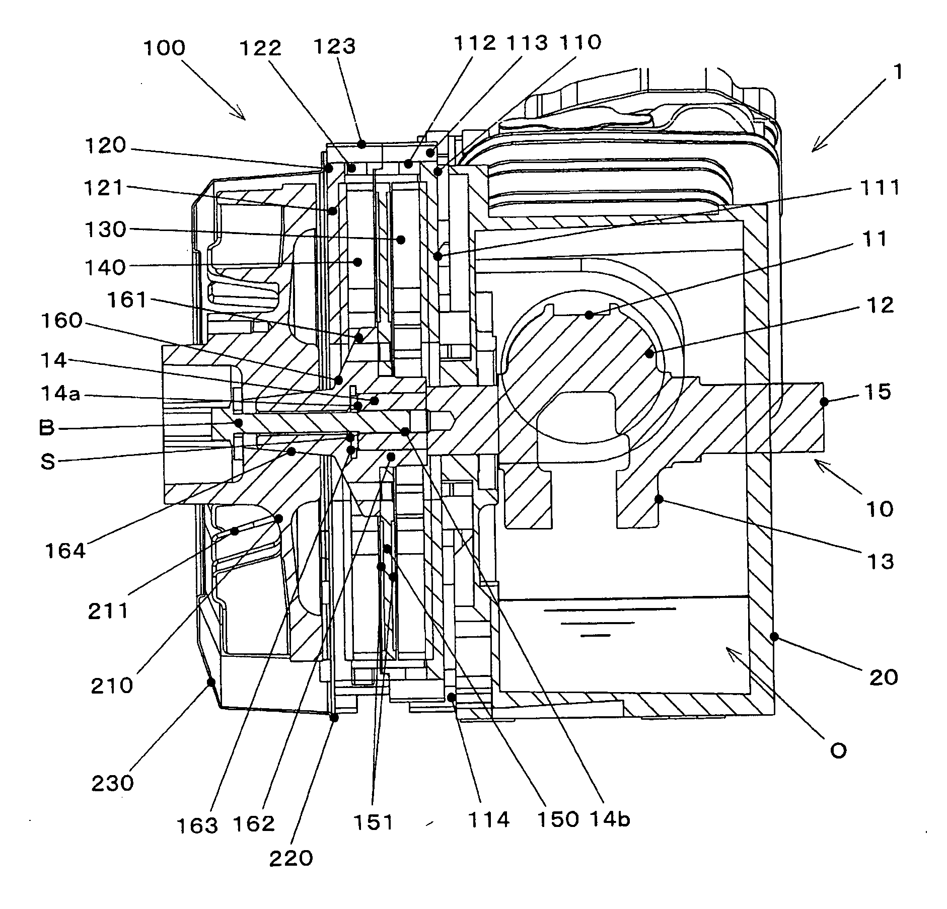
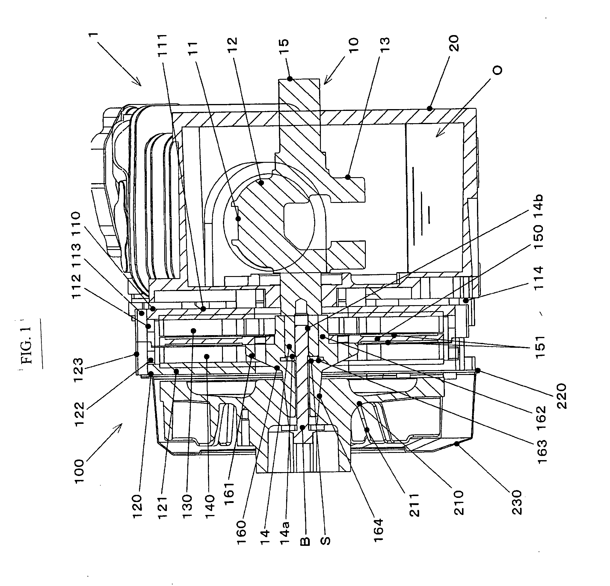
[0024]FIG. 1 is a cross-sectional diagram of an engine provided with the axial gap type generator of the embodiment.

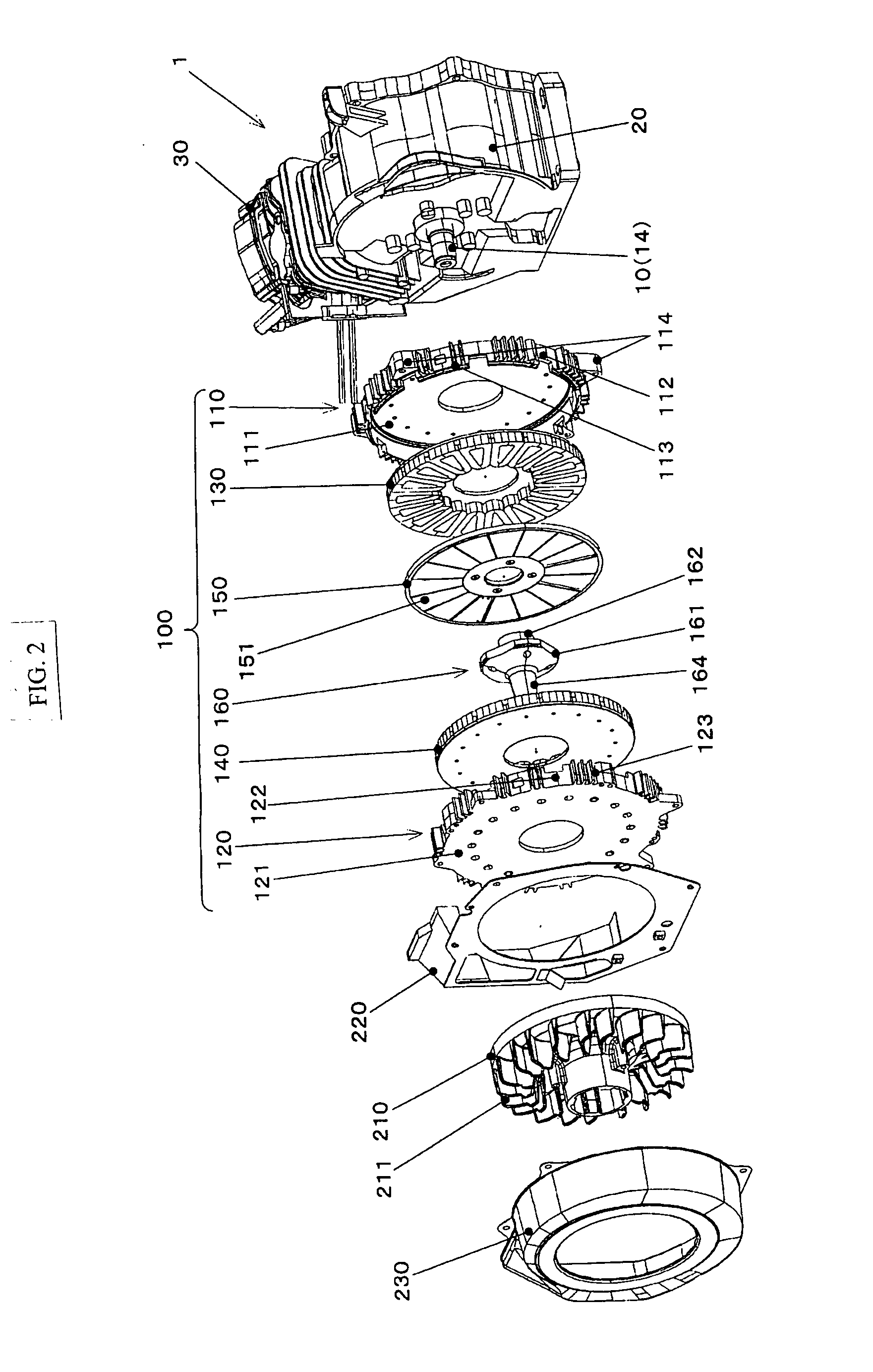
[0025]FIG. 2 is an exploded perspective-view diagram of the engine and the axial gap type generator of FIG. 1.

[0026]An engine 1 in the drawings is, for instance, a single-cylinder four-stroke OHC gasoline engine.

[0027]The engine 1 includes a crankshaft 10, a crank case 20 and so forth.

[0028]The crankshaft 10 is an output shaft of the engine 1 and is rotatably supported on a bearing that is provided in the crank case 20.

[0029]The crankshaft 10 has, for instance, a crank pin 11, a crank arm 12, a crank weight 13 and the like at an intermediate portion thereof, and is supported on beari...


PUM


Abstract

There is provided an axial gap type generator. The axial gap type generator includes: a stator core fixed to a crank case of an engine; a rotor yoke fixed to a crankshaft of the engine and opposing the stator core across spacing in an axial direction of the crankshaft; a first planar section provided in the crankshaft and formed to have a planar shape that is perpendicular to a rotation center axis; a second planar section provided at a base, at which the rotor yoke is mounted on the crankshaft, and disposed opposing the first planar section; and a shim clamped between the first planar section and the second planar section.

Description

CROSS-REFERENCE TO RELATED APPLICATIONS[0001]The present application claims priority from Japanese Patent Application No. 2012-009039 filed on Jan. 19, 2012, the entire contents of which are hereby incorporated by reference.BACKGROUND OF THE INVENTION[0002]1. Field of the Invention[0003]The present invention relates to an axial gap type generator that is mounted on an engine, and more particularly, to an axial gap type generator in which gaps between stator cores and a rotor yoke can be set with satisfactory precision.[0004]2. Description of the Related Art[0005]For general-purpose engines or the like for industrial use, there is known a configuration in which a generator is connected with one end of a crankshaft protruding out of an engine main body.[0006]For instance, a technique disclosed in Japanese Unexamined Patent Application Publication (JP-A) No. H10-4650 provides magnets for power generation at a flywheel that is fixed to the crankshaft end of a motorcycle engine, and coil...

Claims


Application Information

Patent Timeline
Patent Type & Authority Applications(United States)
IPC IPC(8): H02K1/28H02K7/18
CPCF02B63/04H02K21/24H02K7/1807H02K1/28H02K7/1815
Inventor NUMAGUCHI, KAZUYAHISADA, HIROYUKI
Owner SUBARU CORP
Why Eureka
Try Eureka