Method and apparatus for electron-beam lithography

a technology of electron beam and electron beam, which is applied in the field of method and apparatus for electron beam lithography, can solve the problems of affecting the accuracy of the current stage, the factor of deterioration of the precision of the apparatus, and the disorder or degradation of the drawing precision, so as to achieve satisfactory drawing precision

Inactive Publication Date: 2008-03-11
HITACHI HIGH-TECH CORP
View PDF5 Cites 2 Cited by
  • Summary
  • Abstract
  • Description
  • Claims
  • Application Information

AI Technical Summary

Benefits of technology

[0014]The present invention addresses the foregoing problems. An object of the present invention is to provide an electron-beam lithography method and an electron-beam lithography apparatus that can draw patterns with a high beam positioning-precision despite a change in barometric pressure, can ensure a satisfactory throughput, and are inexpensive.
[0017]Moreover, the frequency of calibration and the contents thereof are modified based on a change in barometric pressure, whereby a precision in drawing can be held satisfactory. Moreover, since a barometer alone is needed, the method is inexpensive.

Problems solved by technology

This causes drawing disorder or degradation of a precision in drawing.
In many cases, the change in barometric pressure has caused deformation of a vacuum tank and has been regarded as a factor of degradation of the precision of the apparatus.
When the vacuum tank deforms due to the influence of changes in barometric pressure, the result of measurement of the current stage position contains an error.
However, as far as the electron-beam lithography apparatus is concerned, since the electron-beam lithography apparatus includes a mechanism for transporting a mask substrate or a wafer to the inside of the apparatus and a mechanism for driving a stage or any other internal moving member, a vacuum tank having a completely double structure cannot be adopted.
The adverse effect of deformation of the wall of the vacuum tank cannot be eliminated.
The idea is therefore unfeasible.
It is very hard to calculate a degree of deflection of a correcting precision, which is on the order of nanometers and required as a precision in correction, relative to a structure of several meters high.
There is a high possibility that the required correcting precision cannot be ensured.

Method used


Image

  • Method and apparatus for electron-beam lithography
  • Method and apparatus for electron-beam lithography
  • Method and apparatus for electron-beam lithography

Examples


Embodiment Construction

[0026]Embodiments of the present invention will be described in conjunction with the drawings below.

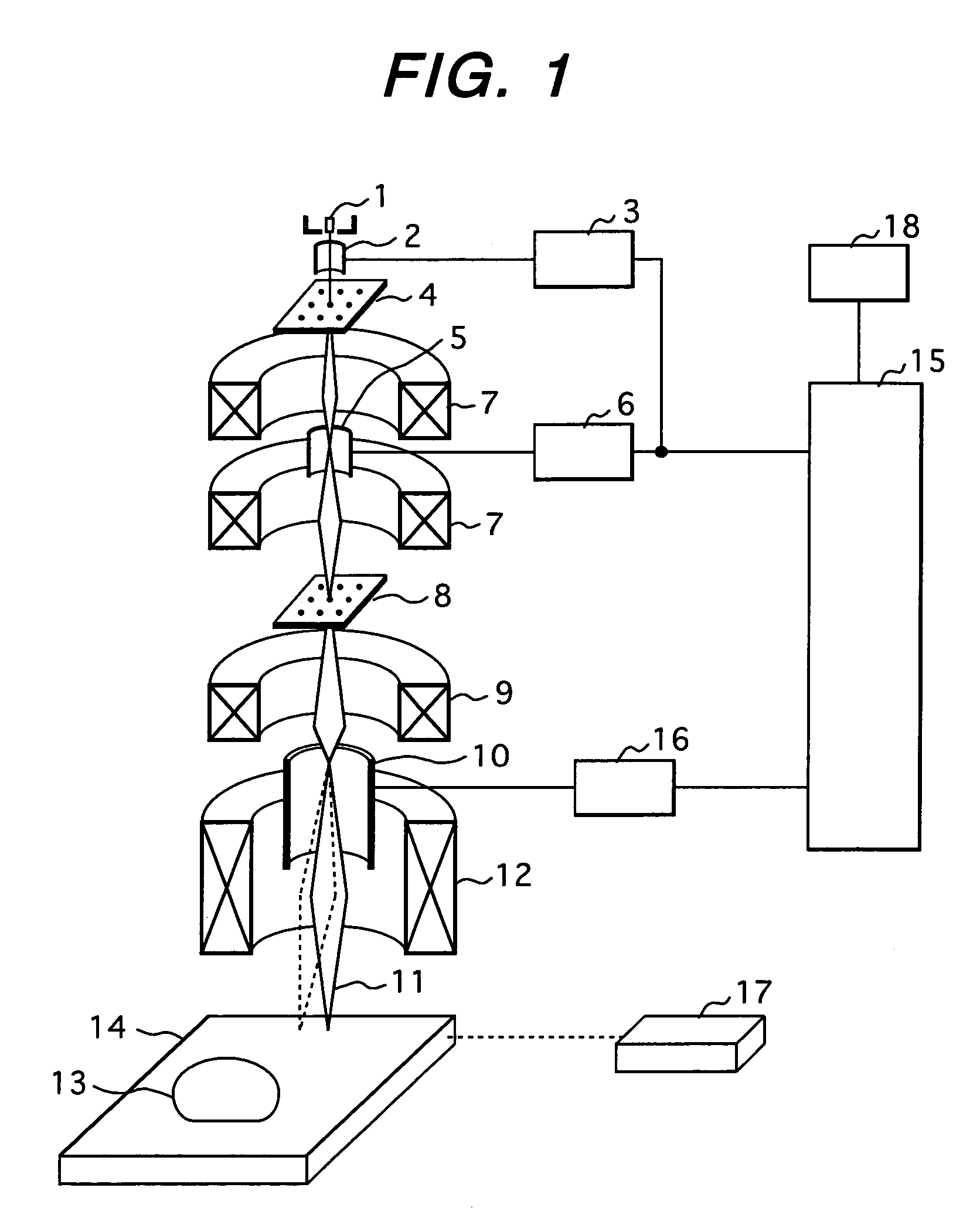
[0027]To begin with, an electron-beam lithography apparatus will be outlined below with reference to FIG. 1.

[0028]An electron beam 11 radiated from an electron source 1 is irradiated to a first mask 4 after being aligned by a beam aligner 2. A beam aligner control circuit 3 controls the beam aligner 2. The electron beam transmitted via the first mask 4 passes through a shaping lens 7 and reaches a second mask 8. When an electron beam is irradiated to the second mask 8, a control computer 15 instructs a shaping deflection control circuit 6 to determine a dimension for the electron beam-shape. The shaping deflection control circuit 6 applies a voltage on the determined dimension to the shaping deflector 5, whereby a rectangular electron beam is transmitted by the second mask 8 so that it will have the determined dimension on a wafer 13.

[0029]The shaping deflector 5 and shaping deflectio...


PUM


Abstract

The present invention is to provide an electron-beam lithography method and an electron-beam lithography apparatus that can draw patterns with a high precision despite a change in barometric pressure, can ensure a satisfactory throughput, and are inexpensive. In the electron-beam lithography method that uses an electron beam to draw patterns on a sample, a difference between a current measured barometric pressure and a previous measured barometric pressure, and an elapsed time between their barometric pressure-measurement points in time are determined. When the rate of the difference of their barometric pressures with respect to the elapsed time is equal to or larger than a prescribed barometric pressure change rate value, a drawing precision is calibrated.

Description

CLAIM OF PRIORITY[0001]The present application claims priority from Japanese application serial no. 2004-208692, filed on Jul. 15, 2004, the content of which is hereby incorporated by reference into this application.FIELD OF THE INVENTION[0002]The present invention relates to a method and apparatus for electron-beam lithography. More particularly, the present invention is concerned with calibration of a precision in drawing.BACKGROUND OF THE INVENTION[0003]Electron-beam lithography apparatus draws patterns onto a sample such as a mask, a wafer, or the like by exposure of an electron beam. Since an electron beam used for the drawing is susceptible to ambient circumstances including temperature, barometric pressure, and magnetism, the position of a beam spot, a focal point, a state of deflection, and a shaped beam size change over time. This causes drawing disorder or degradation of a precision in drawing. In order to correct the degradation of the drawing precision and draw patterns ...

Claims


Application Information

Patent Timeline
Patent Type & Authority Patents(United States)
IPC IPC(8): G21K5/04H01J33/00
CPCB82Y10/00B82Y40/00H01J37/3174H01J2237/31793
Inventor AOKI, YASUKOTAWA, TSUTOMUSAZE, YOSHIMITSU
Owner HITACHI HIGH-TECH CORP
Why Eureka
Try Eureka